Welcome to the Onshape forum! Ask questions and join in the discussions about everything Onshape.
First time visiting? Here are some places to start:- Looking for a certain topic? Check out the categories filter or use Search (upper right).
- Need support? Ask a question to our Community Support category.
- Please submit support tickets for bugs but you can request improvements in the Product Feedback category.
- Be respectful, on topic and if you see a problem, Flag it.
If you would like to contact our Community Manager personally, feel free to send a private message or an email.
Options
Sheet metal "Tangent Joint"?
 eric_pesty
Member Posts: 1,500 PRO
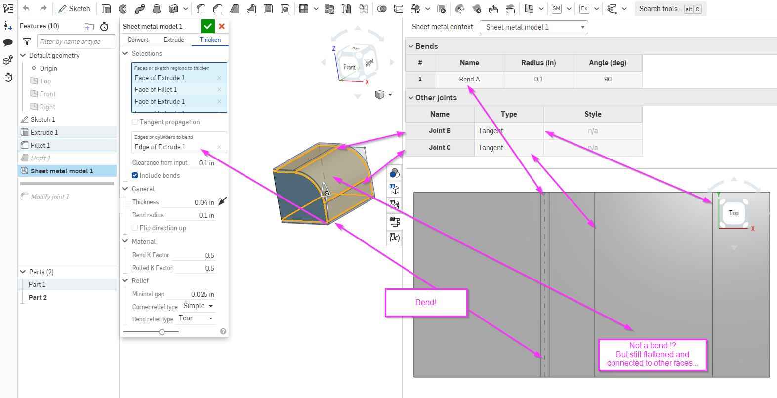
Ran into this today when converting an imported model to sheet metal and bends would not show up on the drawing. It turns out there were no bends defined as it was created by picking one face and using "tangent propagation", which picked all the of the relevant and generated a flat pattern...
However because the bend list was empty there were no "bends" defined. This was pretty confusing as there was a flat view of the part and "flat pattern" available to put on a drawing. The original bends (cylindrical faces) of the imported model had been converted as separate faces with "tangent joints" to the flat ones, I did not know that was possible and didn't notice (when converting a solid with sharp corners it's obvious you have to pick the bends as it will leave the individual faces disconnected if you don't!
After realizing what happened and populating the "bends" section of the sheet metal feature everything was ok...
However this left me wondering why this is even an option, what is it for? Anyone have some wisdom on how/why/when you would use this feature (cylindrical sheet metal faces not specified as "bends")?

Tagged:
0
Comments
The reason this is a separate selection would be so that it can use a different k factor for the rolled sections. It also doesn't require a flat face either side of the cylinder.
IR for AS/NZS 1100
Hmmm, not sure how I would assign a different K-factor since it's created all in one sheet metal feature.
I do see how not needing a "flat" flange on end makes it different than a bend (if a bend is defined as a transition between two flat faces).
I guess it paves the way to non cylindrical faces in the future (I did try to see if it would work on a conic section but it doesn't at this time...)
I guess what I meant to say was that you can choose to not select the faces and they will come in as rolled sections, which have a different k factor.
@S1mon
Under the other joints section in the table, rip joints are also shown, and you can make the rip go one way or the other as a butt joint.
IR for AS/NZS 1100
Thanks for the answer, I haven't run into a scenario where I have needed to do that yet but it's good to know!