How can I make a flattenable square-to-round transition?

Incidentally, I flattened one sector of the bend -externally-, imported the dxf into a sketch and placed it on drawing page 2 by thickening the sketch... Just playing around to learn the program.
Answers
-
I guess your requirement is to have smooth transition for the bend.In order to achieve the same it is required to have sufficient fillets in the sweep path depending on the diameter of the pipe. I seen your document and applied fillets at the corners of bend sketch to achieve smooth bend. See the below images.
1) Bend sketch
2. Sweep profile
0 -
I apologize for the digression in my post, which made it confusing.
My question concerns a way to make a flatten-able square to round transition as shown. Lofting for a solid creates surfaces bent in two directions, which cannot be flattened. Lofting for surfaces works; but subsequent thickening creates solids which I could not manage to unite through the boolean command.
The sweep command creates the solid (duct bend) directly by sweeping through a path of straight lines.
0 -
I am also trying to achieve the geometry as you shown using multiple lofts in surfaces since in solid it is not happening. But eventually after creating in surfaces I am also not able to unite them by Boolean after thicken operation. I remember that we can create similar geometry in Autodesk Inventor sheet metal but not in part module since we can make flat pattern only in sheet metal parts. Such parts always require notches, sufficient bend radius to make it flat which is very well defined in any sheet metal application. I believe that once Onshape will introduce sheet metal, we should able to perform the scenario as required. Can you mention which software tool you used to get above square to round transition?
However, I am also trying to find the workaround method to achieve the geometry what you have shown. I will post it once I find any method.
Thanks0 -
Hello Shashank, I made the transition with Onshape. Triangular sides did join together with the Boolean command, perhaps because the solids overlap, but conical pieces didn't join. I guess these may only have edges contacting with adjacent geometry, which prevents the joining operation.
Lofting between two arches after replacing the vertex of the cone by an small arch, say 0.01 mm diameter, does produce a surface which thickens to a solid that joins the adjacent geometry after thickening. But it's kind of a "dirty trick".
This is perhaps an indication that lofting should be extended to be able to produce this type of seemingly simple geometry.
I am interested to to see if you find other alternatives.
0 -
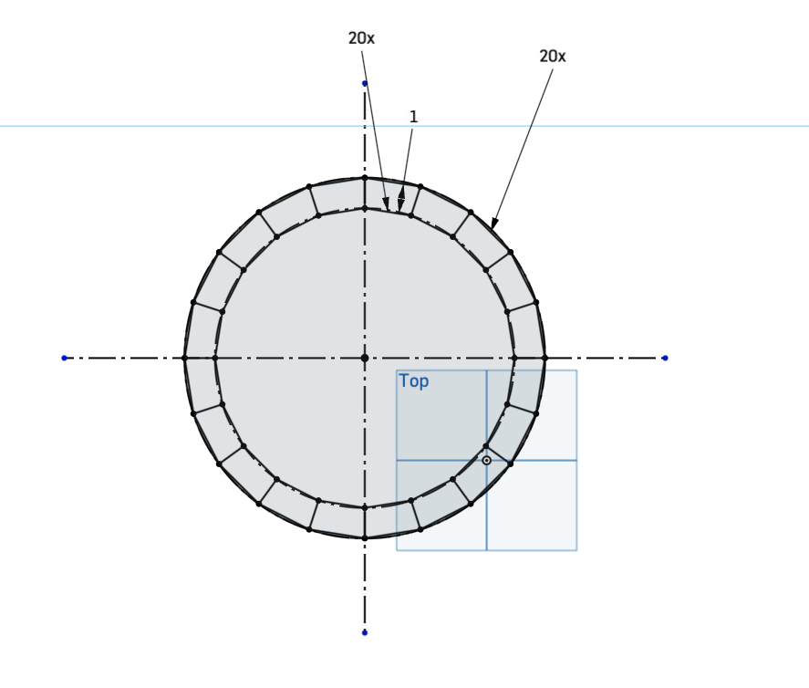
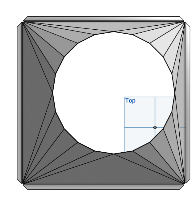
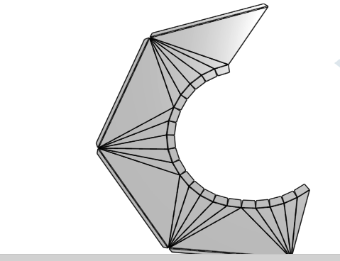
I know this has been dormant for a decade, but since it was at the top of the list for me looking for a solution, I thought I'd throw this out there. In the underlying sketch, add a circumscribed polygon to the circle representing the outlet diameter. Place construction lines to quarter the circle, and make sure that the polygon is aligned with the guides. Set the number of sides high enough to provide a suitable surface (20 worked well for me). Loft from the vertices of the rectangle to the edges of the polygon, and from the edges of the rectangle to the points where the quartered circle meet. This will give you the shape you need.
(Note: My model has an extra polygon to provide tabs for attachment. You only need the outer one circumscribed by the circle.)
 0
-
Very nice! 😎
0 -
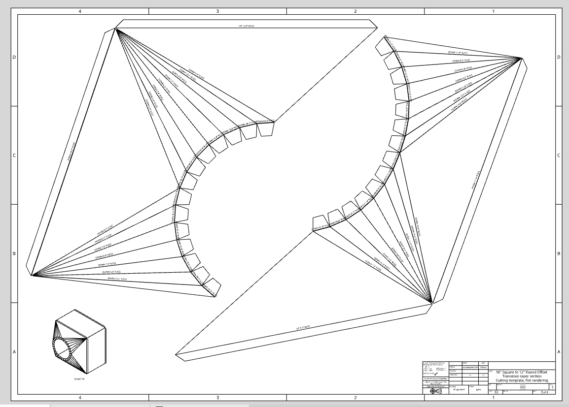
It would be really helpful if there was a direct way to control the number of bends at each corner. Without it, I have to manually adjust flanges or other objects generated at the edges of the bent segments when I adjust parametric sizes. The model generates the number of bends dynamically, and when it adds or subtracts segments, the flange works for segments that stay, but breaks where segments/bends were removed and is missing newly generated segments/bends.
For example, about half the flanges along the curved edge here will break if I shrink the square end, because several bends go missing and several new ones are generated. It's manually fixable, but that sort of defeats the purpose of making the model parametric!
 0