Welcome to the Onshape forum! Ask questions and join in the discussions about everything Onshape.
First time visiting? Here are some places to start:- Looking for a certain topic? Check out the categories filter or use Search (upper right).
- Need support? Ask a question to our Community Support category.
- Please submit support tickets for bugs but you can request improvements in the Product Feedback category.
- Be respectful, on topic and if you see a problem, Flag it.
If you would like to contact our Community Manager personally, feel free to send a private message or an email.
Is there a way to get the Center of Mass of a part to show up in the drawing

I'd like to dimension the location of the center of mass in a drawing. Is this possible?
Answers
-
.
If the part is made of one consistent material, then you could use Approximate Centroid by @EvanReese
This will give you a mate connector which you can reference with a sketch or object however you like..
RENDERCAD
rendercad.ai - Photorealistic product rendering.
▚▞▚▞▚▞▚▞▚
________________________________________________________________________0 -
I'm still kind of creeped out by the fact that the underlying function is called approximateCentroid() and comes with "Warning: This is an approximate value and it is not recommended to use this for modeling purposes that will be negatively affected in case the approximation changes." For showing in a drawing that should be fine.
0 -
Why not like this?:
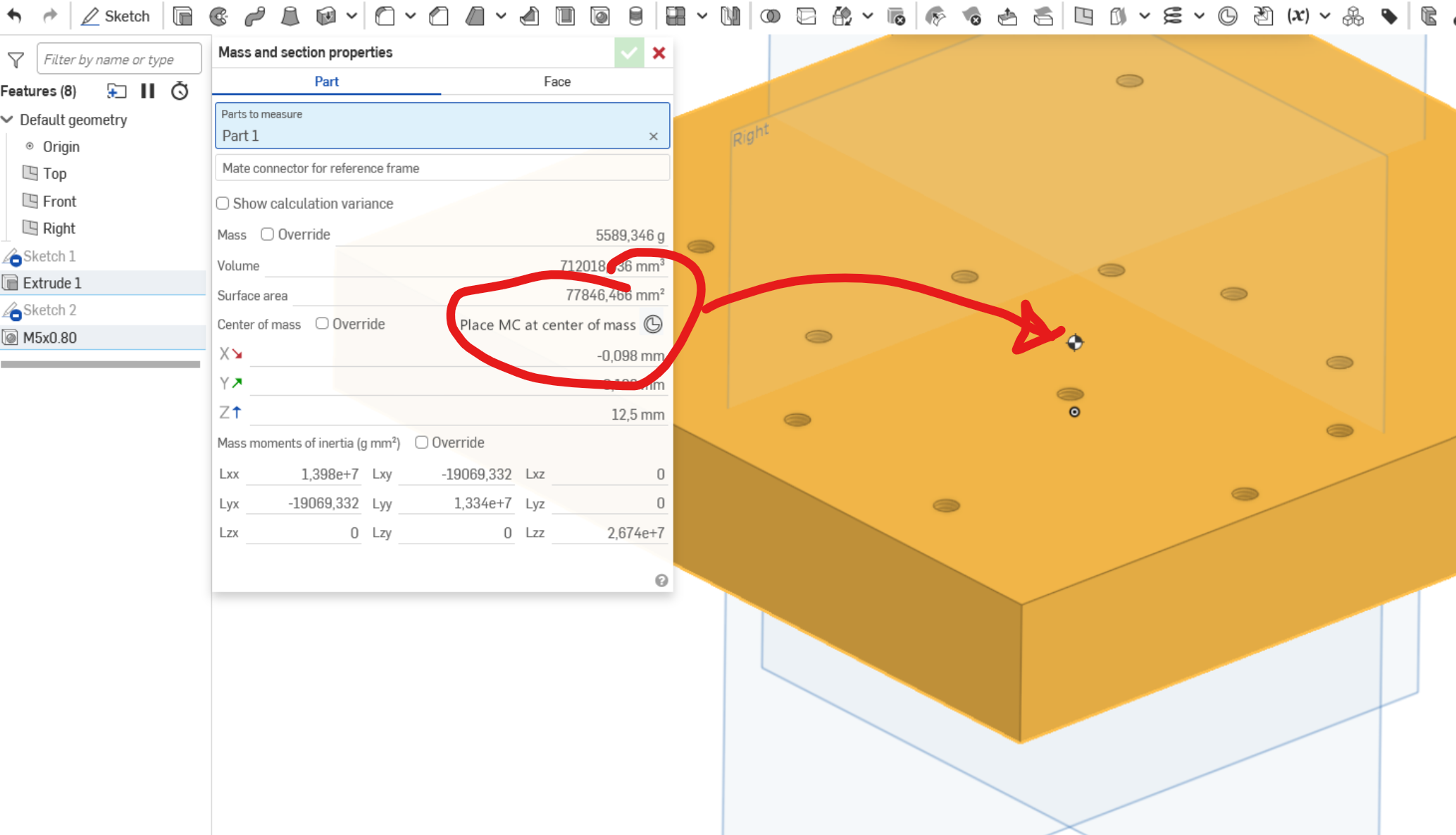 0
0 -
… and if not, there should be a FS that can do that, at least in a part studio: search out the center of mass in a part and place a MC with the part as owner. That'd at least carry through to an assembly and wold be convenient for rotating parts and such. Eventually, it would of course be super helpful if an MC at the center of mass could be created in assemblies.
EDIT: Found it! I was just being dumb: The FS is not called center of mass but "Center of Gravity".
0 -
@martin_kopplow how did you get that to show up? I don't seem to have it. Did you just fake it into your picture?😆
This is a brand new document, I checked the assembly and part studio, and materials have been assigned.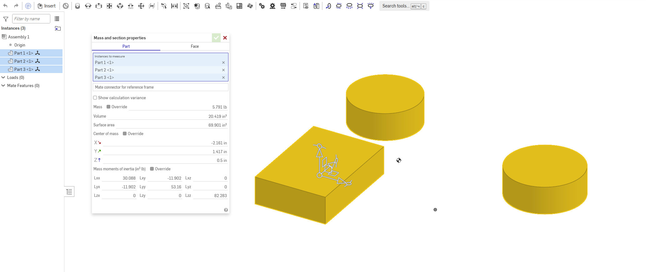
RENDERCAD
rendercad.ai - Photorealistic product rendering.
▚▞▚▞▚▞▚▞▚
________________________________________________________________________0 -
Photoshop. ;0)
Though it looks quite natural and one would expect it just there, right? Q.E.D. It might be about time for an enhancement request, then.
Before doing so, we might need to discuss how his should work and where it should reside.
- At the above place for it would be the most expected location?
- Inside the mate connector edit dialog, for it would enable to place an MC at the CG at any time and for any selection of parts in a part studio or in an assembly?
I think it might be important to have the MC at CG re-calulate after updates to the geometry. That again might be an argument in favour of a FS or a feature tool that could reside near the end of the feature list in a part studio, but where would it live in an assembly?
0 -
Too bad the "part" will most likely be hidden inside bodies in a drawing. Maybe a set of XYZ-aligned sketches? Don't they shine through?
1 -
SolidWorks does this. Why doesn't Onshape?
In a SolidWorks assembly I can calculate Mass Properties. Then there's a button that says Create Center of Mass Feature.
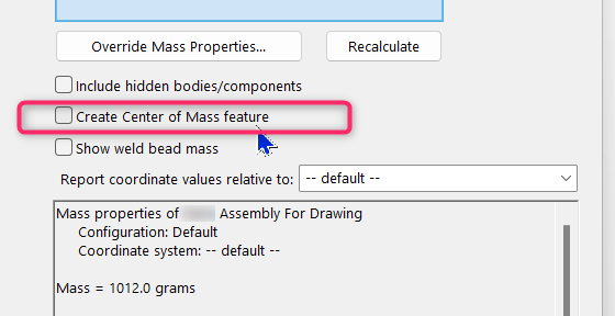
Tick that box, then it adds the Center of Mass as a feature in the feature tree. You can hide it or show it on your assembly.
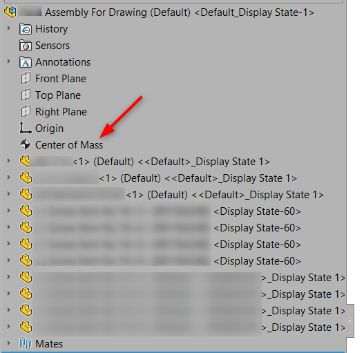
Then in the drawing, for any view you add you can hide or show the center of mass in that view.
You can even dimension to it from any other feature.
Would be nice if Onshape had the same thing.
0 -
Is it possible to modify your CF to then place a sketch on the mate connector and a sketch point on its CofM location, which would allow it to be shown in assemblies and drawings
0 -
@Chris_Beckett wrote: " … Then there's a button that says Create Center of Mass Feature."
I want it! Really. I already needed a CG feature many times already and since I know my old CAD had it, I struggle the more. This is all not about putting a centermak style thingy in a drawing, it is about marking the real and current center of gravity or mass in the model and of course in the drawings. Also, lots of calculations would reference it. For example could a volume of a cutout be driven by the CofM location, to compensate for weight shift. For this reason, it would not be a constant set of coordinates, but a calculated point in space that might even change as design evolves. Think highly dynamic mechanisms or aerospace applications.
0 -
@Jenny_Johnson Sure I just pushed a V6 with a sketch point option.
0 -
If we could use the CofM coordinates displayed by the Mass and section properies tool box as measured values in a variable studio, we'd already be a giant step further, for we could drive a mate connector's offset by these:
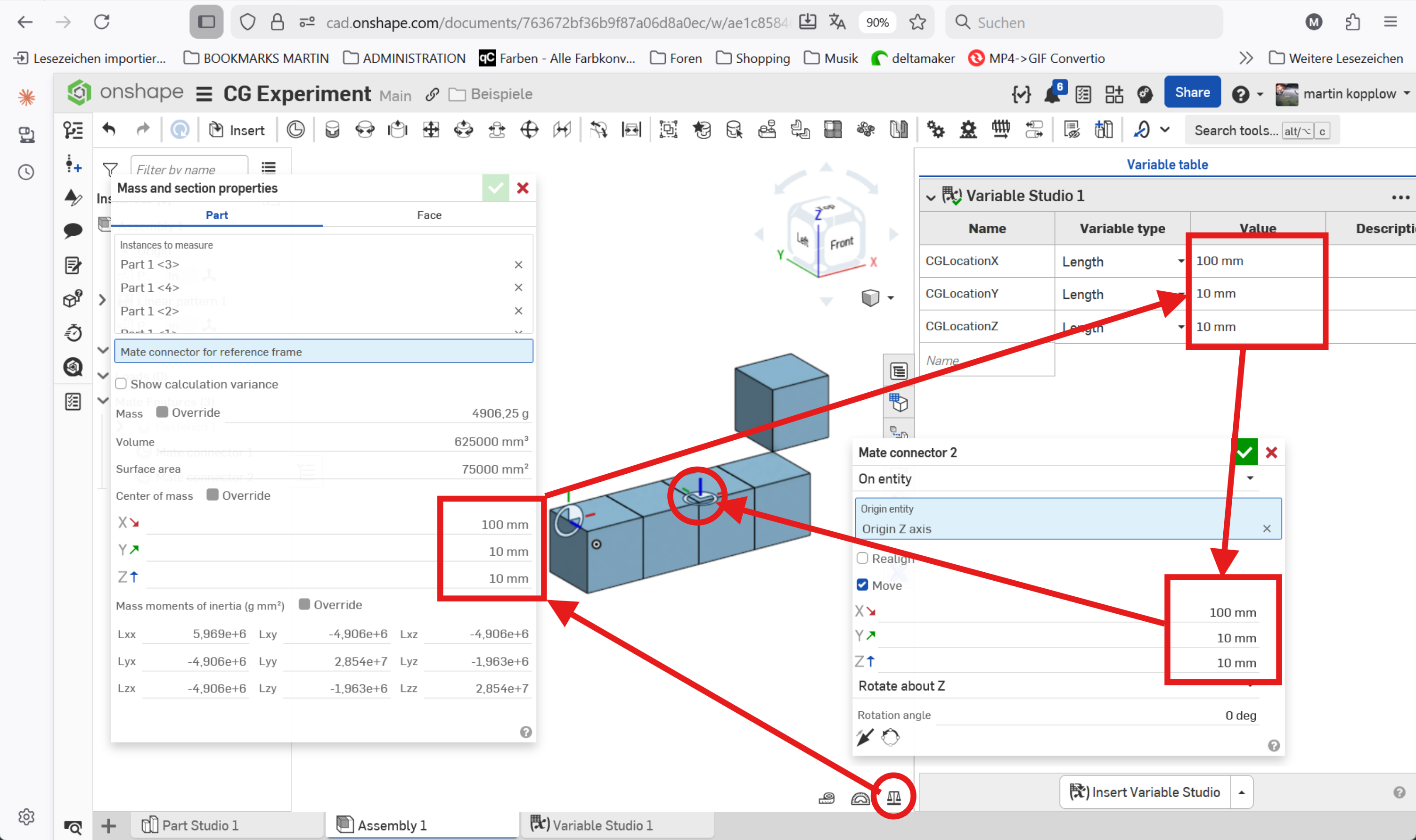
That would open up possibilities to either use that MC for further operations or put a CofM mark upon it for visualisation purposes.
0 -
I just found out that I had asked for this before. Anyway, in case things have changed since:
Is there a way to use the coordinates of the Center of Mass as given (and displayed!) by the mass and section properties tool dialog into a variable? I need the CoM not only to to show up but be referenced in my CAD model. Sample:
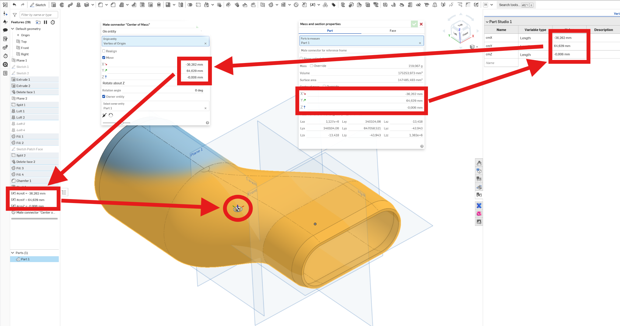
They cannot be picked as a measured value (why not?). Could an FS extract or query them and put them in a varaible table? I could then feed them into a mate connector or a plane to position it accordingly.
0