Welcome to the Onshape forum! Ask questions and join in the discussions about everything Onshape.
First time visiting? Here are some places to start:- Looking for a certain topic? Check out the categories filter or use Search (upper right).
- Need support? Ask a question to our Community Support category.
- Please submit support tickets for bugs but you can request improvements in the Product Feedback category.
- Be respectful, on topic and if you see a problem, Flag it.
If you would like to contact our Community Manager personally, feel free to send a private message or an email.
Best Of
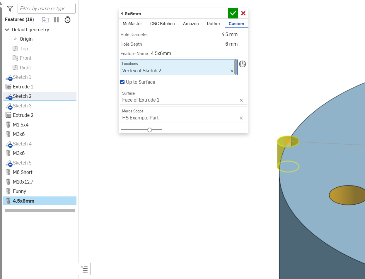
Re: Custom Feature: Heat Set Insert (Threaded inserts for 3D Printed Parts)
I have updated the featurescript with the new CNC kitchen inserts. I have also added a tab called "Custom" where you can type in your own height and depth of insert.
Because I am using the name of the insert to drive the feature name in the tree, I also added a line where you can name what you want your custom feature name to be called. Does anyone more experienced than me know how toggle whether the feature name is set by a variable or just default. That would be very handy for the custom inserts. Right now I am using "Featurename Template: " in my feature call, which makes the feature impossible to rename.

Re: Help with featurescript subtraction
annotation { "Feature Type Name" : "Tube Plug", "Feature Type Description" : "Makes Holes in a tube for a tube plug" }
export const myFeature = defineFeature(function(context is Context, id is Id, definition is map)
    precondition
    {
        annotation { "Name" : "Tube Ends", "Filter" : EntityType.FACE } // Parameter "Tube Ends", filter for Faces
        definition.tubeEnds is Query;
    }
    {
        var i = 0;

        for (var face in evaluateQuery(context, definition.tubeEnds))
        {
            const allEdges = qAdjacent(face, AdjacencyType.EDGE, EntityType.EDGE);

            const edges = [qLargest(allEdges), qLargest(qSubtraction(allEdges, qParallelEdges(allEdges, qLargest(allEdges))))];

            for (var edge in edges)
            {
                var holeFace = qSubtraction(qAdjacent(edge, AdjacencyType.EDGE, EntityType.FACE), face);
                var sketchPlane = evPlane(context, { "face" : holeFace });
                var sketchId = id + ("sketch" ~ i);

                var sketch = newSketchOnPlane(context, sketchId, {
                        "sketchPlane" : sketchPlane
                    });

                skCircle(sketch, "circle1", {
                            "center" : vector(0, 0) * inch,
                            "radius" : .105 * inch
                        });

                skSolve(sketch);

                opExtrude(context, id + ("extrude" ~ i), {
                            "entities" : qSketchRegion(sketchId),
                            "direction" : -sketchPlane.normal,
                            "endBound" : BoundingType.THROUGH_ALL
                        });

                opBoolean(context, id + ("boolean" ~ i), {
                            "tools" : qCreatedBy(id + ("extrude" ~ i), EntityType.BODY),
                            "targets" : qOwnerBody(face),
                            "operationType" : BooleanOperationType.SUBTRACTION
                        });

                i += 1;
            }
        }
    });

Re: LLM powered Autocomplete
So far, my experience is that with the limited training data available (mostly very proprietary), AI CAD tools that can actually understand things like materials, tolerances, assembly constraints, etc. are very very primitive. There are a lot of demos of things where you can make very basic shapes, but compared to writing, programming and math, AI ability in mechanical engineering is a lot further away.
That said, the demo of the "model assistant" in the video linked from PTC/Onshape is interesting. Most of those future demos in the video seem very scripted and perhaps smoke and mirror (fine for directional stuff), but I believe they're at the level of stuff that is possible. The idea of, I need to make a bunch of simple changes to this part. I could theoretically give that task to a junior engineer while I do something more complicated, or I could use this agent. Yeah, sucks to be a junior engineer at that point, but the reality is that if we don't all get good at using better and better tools, we will lose out to people and companies that are, You can't sit around and use files and hand drills while others are using 5-axis CNC machines and expect to compete in the same space.
 S1mon
S1mon