Welcome to the Onshape forum! Ask questions and join in the discussions about everything Onshape.
First time visiting? Here are some places to start:- Looking for a certain topic? Check out the categories filter or use Search (upper right).
- Need support? Ask a question to our Community Support category.
- Please submit support tickets for bugs but you can request improvements in the Product Feedback category.
- Be respectful, on topic and if you see a problem, Flag it.
If you would like to contact our Community Manager personally, feel free to send a private message or an email.
Best Of
Re: Virtual Event May 14th, 11:00 AM EST, Faster Design Cycles With Custom Truck
Looking forward to it!

Re: Virtual Event May 14th, 11:00 AM EST, Faster Design Cycles With Custom Truck
Cant wait to help create a new Onshape World Order with all of you chill dudes B-)

Re: FeatureScript Library (New Custom Features!) 💎
.
 Boolean Composites
Has been added to the CADSharp FeatureScript Library!
This custom feature has the ability to handle composite parts as well as standard parts when performing boolean operations.
www.cadsharp.com/featurescripts


Re: Animating assemblies by dragging with the mouse
You need to fix/anchor one part (from the RMB context menu of the item in the tree). Else, things will move erratically. Also, consider applying min/max limits, so things don't go too far out of specs in any one direction.
Re: segment gear
Easy: Make a full gear (using THIS) and cut away what is not needed.
Re: Rotating a sketch rectangle
There isn't anything like a skTransform function (at least not one that's publically documented). When making sketches in FS, it's more important that you get your initial coordinate system correct, instead of creating a sketch somewhere and then moving it. That's part of the reason that the sketch documentation says constraints are mostly unnecessary when sketching in FS, you can usually pinpoint exactly where you want it with some good vector math. Another approach could be to sketch and extrude, then do the opTransform function (this depends on the use case of course).
If you want my advice though, I would recommend staying away from sketching in FS. What I do almost every time I need sketches generated by a custom feature is I make a part studio with that sketch in it, set it up with configuration parameters, then I just derive the sketch in using the custom feature and from there it's much easier to place/rotate the sketch entity. It's also way easier to edit that sketch since you can just edit it in a part studio instead of redoing your logic for constraints in FS.

Re: Looking for Beta Testers – Try Out OnDisplay!
Aaaand…. yet another update!
- We finally got rid of a lurking bug that showed up only with big models. This was a nasty one.
- We made scaling models accept a larger range (from 1/10 to 10) and as models scale, their bases remain grounded on the floor plane.
- Improved performance!
- Some more fixes here and there, some colors, better positioning of the camera, etc.
See short video!

We're now looking into composite parts, probably the last nut to crack before we go live...
Thanks!
Stephanos

Re: Looking for Beta Testers – Try Out OnDisplay!
Hi all,
One more update (v0.1.3 Beta) is live, and it's pretty big :-). In this new version:
- We load colors from Onshape (at last!)
- Ground plane can be added or removed, and the model is located on it precisely
- New, improved automatic calculation of explosion directions, keeping the largest part in the model fixed
- Selected objects remain selected after you assign colors or materials
- ... and a lot more!
We're still working on these two items, but we hope to crack them very soon:
- Loading parts from linked documents
- Loading composite parts
Thank you, and stay tuned!
Stephanos


Re: Home projects show and tell
Cat camera holders:

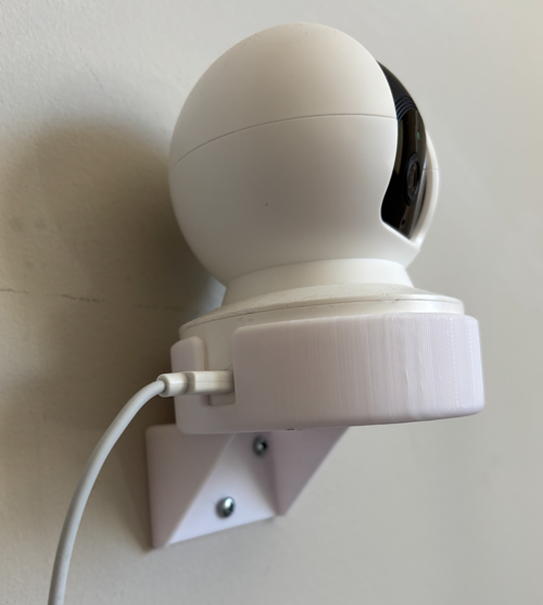

https://cad.onshape.com/documents/07023616aede3c8970f63a11/v/86aa465afeb9a908ceda8f17/e/d9fabd784f9de54dc6c3f9aa