Welcome to the Onshape forum! Ask questions and join in the discussions about everything Onshape.
First time visiting? Here are some places to start:- Looking for a certain topic? Check out the categories filter or use Search (upper right).
- Need support? Ask a question to our Community Support category.
- Please submit support tickets for bugs but you can request improvements in the Product Feedback category.
- Be respectful, on topic and if you see a problem, Flag it.
If you would like to contact our Community Manager personally, feel free to send a private message or an email.
Best Of
Re: 3d nest nesting CNC CAM
Only now and then do I need nesting. Mostly for laser cutting, if I don't just leave it to the laser booth to do the appropriate nesting for the sheet they have in stock (which may already be missing some areas). So, nesting actually makes little sense within my own CAD document.
Nesting FS does only work on the part studio level. I think that is an issue.
If I need ultimate control, I usually create a new nesting assembly tab in which I import a sketch of the sheet or block and then insert my parts as needed (e.g. oriented relative to the grain or surface pattern). That way, I get a reliable list (BOM) of the actual nested parts, and they stay connected to the CAD model, in case I make changes. It requires manual work, though.
If I could make a wish, I'd wish that there'd be a nesting tool that searches an assembly for parts that were tagged for e.g. milling, routing or laser cutting, have a common material assigned, and put these on a sheet of user specified material and size in another tab. It would of course update after changes have been made to the parent assembly and it would have an option to add spare parts to the nesting.

Re: Custom Feature: Query Variable+
@Derek_Van_Allen_BD
I wish you a happy and peaceful winter solstice.
please find the
 QueryVariable+ icon attached.

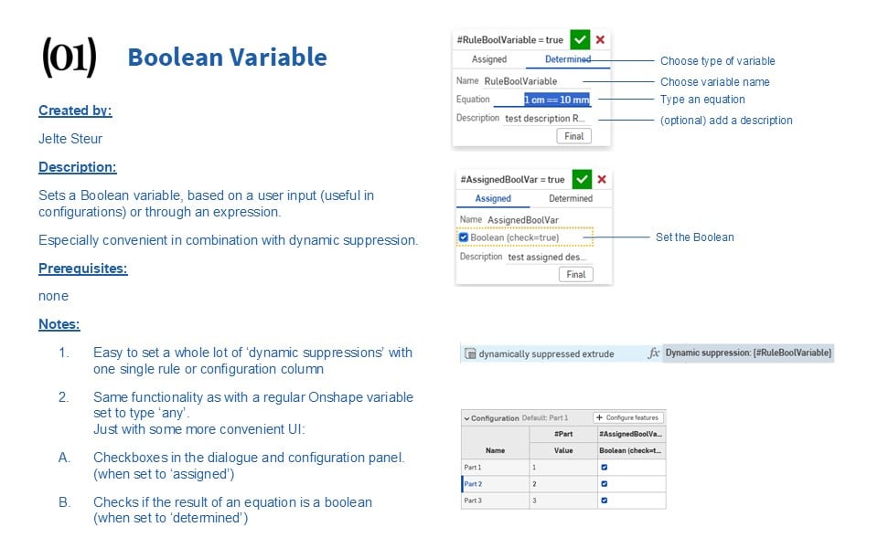
new custom feature: Boolean Variable
Happy winter solstice to everyone!
I was grouping some dynamic suppressions in a configurable document and creating a regular variable, setting it to 'any' and creating an equation, (or typing "true" manually.)
This bothered me, I figured this should be easier if I'm going to do this a lot.
so I created a dedicated:
Boolean Variable
Re: Custom Feature: Amalgam Tag and Amalgamate
@jason_ryan337 meant to get back to this earlier but had a few other projects come up. Here's a document and a couple example gifs of usage to show intended workflow for you and anyone else browsing this thread later:
First you draw a standalone part studio that contains geometry you wish to replicate in other documents. For this example I took a cabinet hinge from McMaster Carr and drew the standard cut geometry that applies to those hinges everywhere they're used. I then tagged the hinge bodies as new for insertion and all the subtractive tool bodies which turns them transparent pink to let you know they're not supposed to be real part geometry. No union tools tagged because we're only doing cuts on the bodies we're applying this amalgam to.
Then in your downstream documents you just need to select the tagged amalgam tool studio and whatever configuration you wanted to pull from it and specify your boolean merge scopes for subtractive and additive operations and whether you're including the insertion parts, grab your location points, and let the tool do the magic.

Re: How can I make this pill shap cut through the other body like I was moving a hot body through snow?
@Derek_Van_Allen_BD, good point. I am sweeping a 2D face. That will not ensure that a 3D solid will make it around the corner.
@daniel_rodríguez_rivero, here's if close is good enough:
https://cad.onshape.com/documents/8599b97967bf83834614d764/w/37f28f6d0a15921bdd09c854/e/184e17c1c860e887f36c2652

Re: FeatureScript question. allowing variable names with/without spaces
Using spaces in identifiers would screw up expression parsing, you can make multiword descriptions for variables, but keep the name short enough to let it be conviniently used in expressions
 Konst_Sh
Re: Fusion to Onshape: Using a part to make a cut in other parts
@martin_kopplow for kicks I decided to torture test the amalgamate feature with a part using the worst performing geometry I could think of just to see how it would do. 70+ second rebuild time in the seed studio for a single knurled "bolt" with knurled threads, but with some clever configuring to simplify geometry I can get a build time of ~ .3 seconds to swiss cheese this polyhedron with perfect holes to hold a bunch of them. I also made it so the high detailed version of the studio had the tag feature suppressed just to prevent anyone from actually attempting to use the 70 second rebuild time version of the model for renders as tool geometry. The inner workings of both our methods rely on the same derive architecture in reality, all my feature is doing is wrapping that up into a tighter UI to minimize the number of extra steps you need to take on the import side of things.
Re: Re-scaling imported DXF
I agree the import dxf functionality is a bit crude. I see other forum users have said that "Onshape never assumes constraints". I kind of get that. But if a polyline is a closed polyline, it could at least constrain the end points. or have a tick box to do so. It would not have to be all coincident end points, just points of a closed polyline. I'd also like it to recognise if an imported line is aligned with the x or y axis of the sketch, and if it is, have a tick box option to lock (all) to horizontal /vertical constraints.

Configurable Parts Library in Part Studio or Assembly?
Currently, I am making a library of our purchased hardware at my company. I model a bolt for example in the PS, with configurable variables and fill in a table in the assembly level to create a list of size choices, material, color, part number etc.
Then in the models I need the hardware in, I grab the bolt size needed from a list in an assembly.
Is this the correct way to do it, or is it best practice to contain it in 1 part studio and not go to assembly level. I have seen both ways. What is the reasoning behind why one is better than the other?
I can share a file if needed. Thank you all
