Welcome to the Onshape forum! Ask questions and join in the discussions about everything Onshape.
First time visiting? Here are some places to start:- Looking for a certain topic? Check out the categories filter or use Search (upper right).
- Need support? Ask a question to our Community Support category.
- Please submit support tickets for bugs but you can request improvements in the Product Feedback category.
- Be respectful, on topic and if you see a problem, Flag it.
If you would like to contact our Community Manager personally, feel free to send a private message or an email.
Best Of
Re: Is it possible to set a minimum & maximum value for a sketch dimension ?
To be fair, that's exactly what those functions do in every other programming language in existence. max returns the maximum value among its arguments, and min returns the minimum value.

Re: Trying to extrude text but can't filter out inner loops.
skText(...);
skSolve(...);
const sketchRegions is Query = makeRobustQuery(context, qSketchRegion(sketchId, true));
opTransform(...);
opExtrude(... { "entities" : sketchRegions, ... });
DavisCCR

How to export decal images?
I have a model with decal images applied to faces and I'd like to export it to COLLADA format (.dae), however the decal images are not included in the output. What can be done? Thanks!

Re: how is this sketch not fully defined?
There's nothing constraining the endpoint of the line (assuming you are talking about "sketch1" at the bottom)
Anything blue in your sketch is not fully constrained…


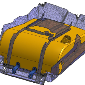
Re: how do I create a tank cover with thru holes?
I changed these two things in your model…

Also try to remember the direction of the hole will be determined by the sketch plane of the points you are selecting. so the issue with your troubles was that the point you were selecting was created in a different plane orientation than the top of the lid.
 MDesign
Re: Vehicle coordinate system
I've been doing vehicle prototyping stuff for Volkswagen for decades, and they also put the origin on the center of front axle, utility and passenger cars alike. While the origin location is free to choose for a job, it is not specifically important for this discusssion, though. Also, pointing the main axis in whatever direction we like is relatively free already. The main question appears to be whether we use a left-handed or right-handed coordinate system, and whether we can assign view labels to the world planes (and have the cube and the drawing views follow or vice versa).
So, I could imagine that choices as follows should already fix most issues:
- Option to set global "Object" vs. "Vehicle" view labels. This would take care of having the left and right side consistent with front and back view.
- Option to select "right-handed" vs. "left-handed" coordinate system (equivalent to Z is up/down). This would take care of inverted Z-axis in aerospace and conventions for pos. or neg. X in some auto manufacturers.
- (Advanced option to revert every axis direction individually. In case everything else fails.)
The combination of those would provide quite some freedom of choice. It'd be difficult to merge the label settings seamlessly with the axis direction, though. This would probably be a GUI issue in the first place. If there was a settings GUI, with the default world system displayed in the background, and a view cube and axis manipulator overlaid on same origin, that could both be moved and snapped to the valid positions, and clicking on either of the three axis or view lables inverting it, that could possibly go a long way. I might need to illustrate that one to make it clear, but I trust in your imaginative powers for now. Maybe it could be incorporated right into the view cube, by adding an edit mode to it.
I support the idea of a corporate setting for a default world coordinate system, that could be overrun by user.

Re: In-context modeling feedback loop – am I doing it wrong?
@eric_pesty I wrote a publish geometry FS this morning after seeing the video.