Welcome to the Onshape forum! Ask questions and join in the discussions about everything Onshape.
First time visiting? Here are some places to start:- Looking for a certain topic? Check out the categories filter or use Search (upper right).
- Need support? Ask a question to our Community Support category.
- Please submit support tickets for bugs but you can request improvements in the Product Feedback category.
- Be respectful, on topic and if you see a problem, Flag it.
If you would like to contact our Community Manager personally, feel free to send a private message or an email.
Best Of
Re: Generating loft causes problems
Thank you very much! This generated the loft as I wished.

Onshape but offline, called OFFSHAPE
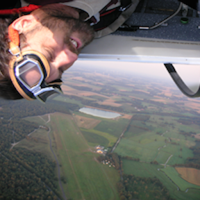
Onshape is awesome. It’s the future of CAD. But sometimes the future doesn’t have Wi-Fi. Like when you’re on a plane, long road trip, or when the only place you can find some peace and quiet is in your anechoic basement dungeon
In those dark, lonely times, all we want is OFFSHAPE
1. Disconnect from Onshape – Screen fades to dark mode, Offshape logo appears, maybe even some secret Easter-egg features?
2. CAD using your own machines computing power
3. Reconnect later and instant sync like nothing ever happened
✨ OFFSHAPE™ – For when you can’t be ON… you can still be OFF
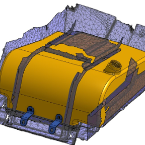
Re: Using a twisted face to split parts
I'm no airplane design expert or even an ametuer but wouldn't it be easier to start with the surfacing of your wing and build the parts based on that skin?
 MDesign
Incomplete fonts or ... how do I find which unicode characters are actually supported?
Recently I needed an arrow on the surface of a part.
I could model the arrow, but onshape has a text tool and many fonts, and unicode has a range of just what I want (https://unicode.org/charts/nameslist/n_2190.html) which would be fine for this model.
Its a little tricky to enter unicode 2192 (→) into the Text tool (In the end I used windows 11 Notepad to create the character : e.g. type 2192 and the Alt X) followed by copy and paste into the onshape "Edit Text" dialogue.
Hurray! It appears to work. The arrow is in the edit box and more reassuringly also in the example window I see my arrow in the target font.
BUT… this is not then reflected in the part. Instead I get a rectangle, implying an unmodeled character to me. Same for the other Arrow codes I tried.
This seems to imply the font libraries aren't mapped to the on-shape modeling through some maths, which is a bit of a surprise.
Trying some of the available fonts I do find success with Arimo but fails with many others (e.g. Allerta, Baumans as examples).
My issue is not the completeness of the coverage in a particular font, but that I haven't found a usable way to discover what is available with each font. Trial and error doesn't work given the range of fonts, especially when the edit dialogue display does not reflect what will be modelled on to a part.
Re: Strandbeast motion problem
That is not a problem specifically with Onshape, it is a design flaw. The frame, the two arms and the middle rod form a parallelogram. When rotaing, there is a mathematically ambiguous position when the arms and the rod are in parallel position: Then, the direction of rotation can 'flip' and still be mathematically valid.
You need to synchronize the rotation of the drive shafts. In the CAD model, the "Gear Relation" would do the job, but you'd still shoot yourself in the foot in real life, if you don't add that synchronisation in some sort of hardware.
If it is going to be all rods, no belts, then it might look somewhat like this:
Also, you might want to make subassemblies. That'd make it much easier to handle.
These Strandbeesten all sem to suffer from Lemming Syndrome. They run more or less downwind until they hit an obstacle or reach the the waterline, get cornered there and finally go extinct. I'd like to see one change it's behavioural principles, maybe creep upwind again and try another direction.
Re: Modeled Threads
https://cad.onshape.com/documents/5c0528b62c1fbb13a2a0e739/w/9f9185ce078357d93c7d0853/e/b2ea3d8356d9673fbe6024c9
https://cad.onshape.com/documents/6b640a407d78066bd5e41c7a/w/4693805578a72f40ebfb4ea3/e/7886aa5aee640497f4eb6265
Modeled threads are computationally expensive and can therefore slow down performance. Most people don't need them modeled as they won't be CNC machined in a traditional sense but will use special tools. People that need to machine them from scratch will likely also need to manually model them as it might be a very specific geometry.
Most of the time when people want to have modeled threads it is because people want to 3d print them for prototyping or their hobby projects.
