Welcome to the Onshape forum! Ask questions and join in the discussions about everything Onshape.
First time visiting? Here are some places to start:- Looking for a certain topic? Check out the categories filter or use Search (upper right).
- Need support? Ask a question to our Community Support category.
- Please submit support tickets for bugs but you can request improvements in the Product Feedback category.
- Be respectful, on topic and if you see a problem, Flag it.
If you would like to contact our Community Manager personally, feel free to send a private message or an email.
Best Of
Re: Countersink with head relief
The enemy of the good is the perfect.
It would be great to have some defaults which make some sense and are related to real hardware, but it's likely that "head clearance" height dimension is going to be highly dependent on the context and design goals, not the hardware itself. Right now, I can't use the hole feature to make this shape, and unlike a regular counterbore, there's no quick hack with move face to get this geometry from a countersunk hole. About all I could do is use a counterbore and add draft, or I just have to revolve a cut and pattern it.
 S1mon
S1mon
Re: Countersink with head relief
Think this is pretty simple - maybe I am missing something. We just need two more options added to the countersunk hole - countersink/counterbore diameter and counterbore depth. See example below (from Solid Edge).PeteYodis said:Yes, this is a known need for sure. But to explain further... you need to be able to pick which particular fastener type you want to add a relief for. There could be several different valid options that would all require differing amounts of relief based on head geometry. It's possible an improvement like this will really start to pair holes with content.

Re: New Custom Feature: 8020 "3030" Profile Converter
Hey @joshtargo there isn't an "official" Onshape 8020 profile library the way you might be thinking.
Something you could make work, however, is to add the frame profile selection code from frame.fs in to your custom feature. You can look at frame.fs ~62 where the profile library is accessed. You can follow the codepath of how this profile is eventually used to make sweeps:
doFrame > getProfile > sweepFrames > doStablePaths > … > doOneStablePath (there are branches off this codepath but this is the simplest). Eventually you get to sweepOnePath and sweepStartingEdge, where the profile is pulled out, patterned to the "start" of the edge, then swept.
The frame toolset is fairly large and complex but you don't need very much of it to get the behavior you want (single straight segments). And in your own code you could probably treat each segment as a separate element and create a 9-pt manipulator for them just by lifting it out of the frame.fs code.
Re: Adding 9-pt manipulators for each path (as you and @S1mon propose above). Seems like a good feature request.
 jnewth
Re: New Custom Feature: 8020 "3030" Profile Converter
i can not edit my previous comments (the text disappears when I click edit). but as i was saying, it's nice to use cuboids during design and then convert all at once at the end. I was gonna modify Frame, but it's way too complex. so i wrote my own thing.

Tangency flipping on sweep profiles...
Help Modeling Pipe with Clocked Bends in Onshape
Hey folks,
I'm hoping someone can help me troubleshoot a problem I'm running into while trying to model a parametric pipe system in Onshape. Ultimately, I'd like to create a custom piping tool using FeatureScript, but I'm starting by manually building the geometry in a Part Studio—and I’m already hitting some snags that make me think this will be trickier than expected.
Here’s a video showing the issue (linked below), and I’ll do my best to describe it here: https://youtu.be/5n34GXwETfY
What I'm Trying to Do
The concept is simple: a pipe composed of straight segments and fixed-radius bends. All pipe diameters and bend radii are constant for now.
- The pipe begins with a straight segment L0.
- At the end of L0, there is a bend with angle B1, followed by another straight segment L1.
- At the end of L1, I begin the next segment. This involves:
- A bend B2
- A clocking angle C2 to rotate the bend around the previous straight segment (L1)
- A new sketch plane based on that clocking angle
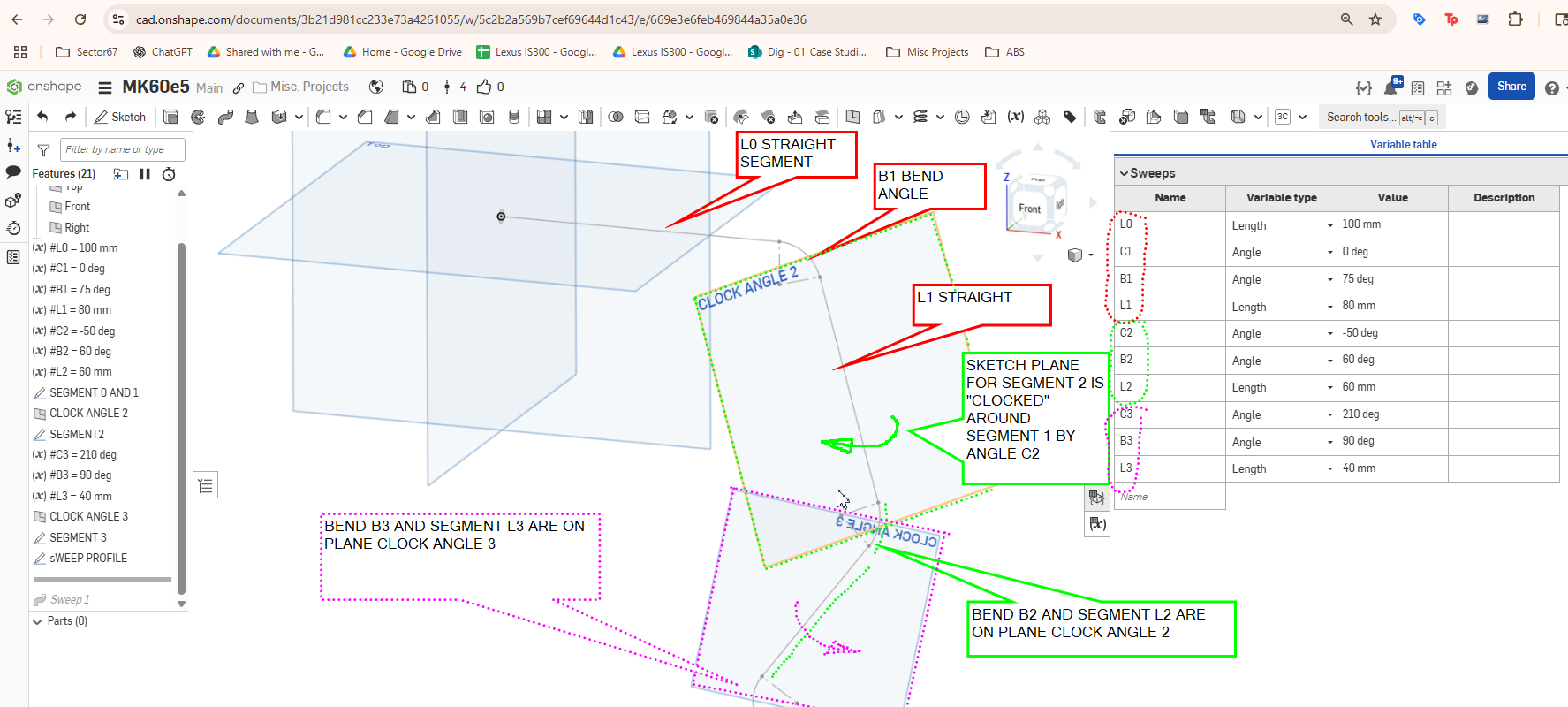
This process repeats: each segment consists of a bend (with a clocking angle) followed by a straight section. I'm driving all of this with a variable table.
The Problem
Everything works fine within certain ranges of angles. But when I change the bend angle or clocking angle, things start to break down. Specifically:
- The tangency on the bend segment often reverses unexpectedly
- I suspect the normal vector of the sketch plane flips, causing the arc I use for the bend to flip directions
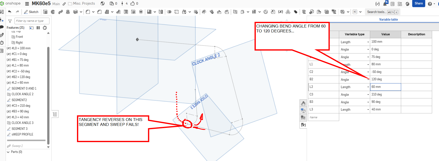
This behavior makes the model unstable and unpredictable, which obviously wouldn’t work for a scripted solution down the line.
What I’m Looking For
- Is there a better way to handle this kind of construction in Onshape?
- Is there a known trick for stabilizing sketch plane orientation when chaining arcs and rotations like this?
- Would FeatureScript help avoid this kind of instability, or would I just run into the same reversal issues?
I’d love to hear any suggestions or strategies. I'm decent with Onshape modeling but still pretty green with FeatureScript—any guidance would be greatly appreciated!
Thanks!
—Dave
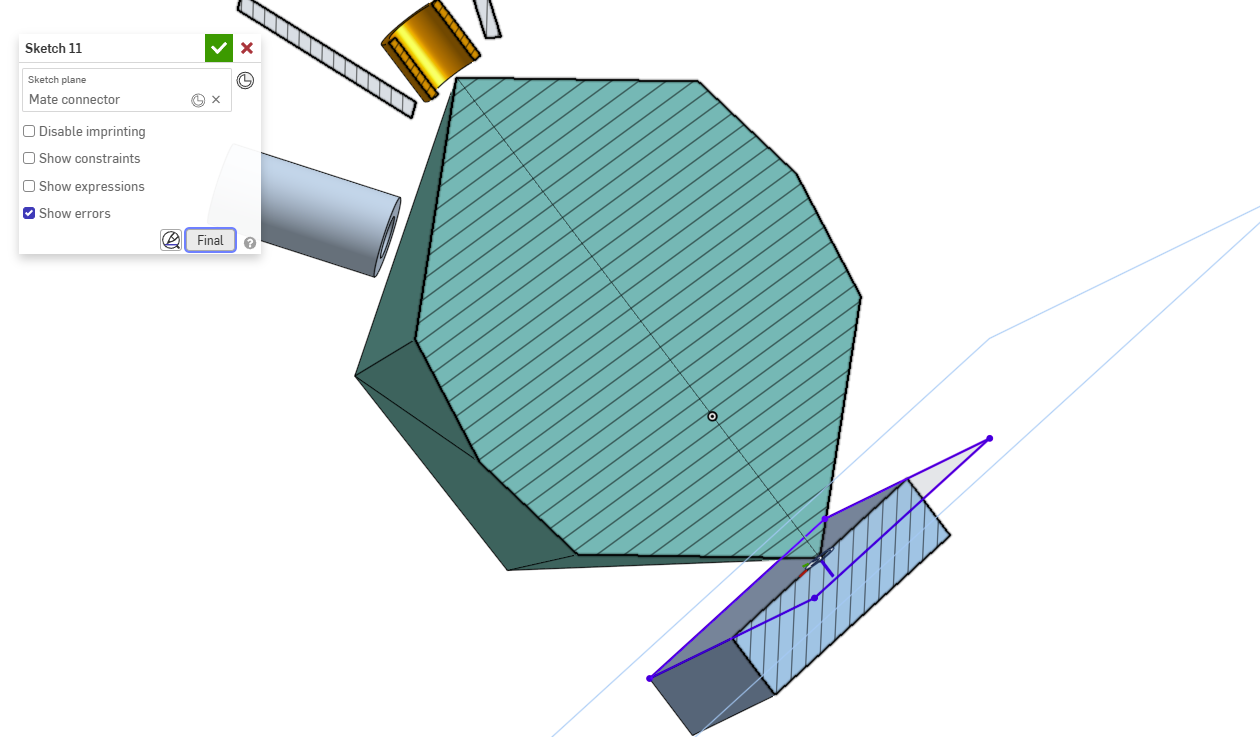
Re: How to create a work plane on these points
SRY miss read post.
Here is an other way. Used 3d fit spline across 2 points. Use the end of the line for sketch mate connecter.

Re: Merge branches when tab has been moved to another document?
Yeah I had a team member do that with a larger project not too long ago and it was something of a debacle trying to wrangle the logic and order of operations to merge things back into one branch. We've since implemented an unofficial policy of not moving things out of the workspace while there are multiple branches live unless you want to master time travel and parallel universe manipulation.

Re: How do I create a simple planar surface bounded by a sketch?
@GregBrown - OK I'm amazed that's the work around. Don't know why there isn't a planar face option. I don't think I ever would have found that. Thanks!
Re: spline/bezier-like with a bias towards circularity
A good way to do this is with a proper NURBS curve, which you can make with the Control point curve custom feature.
This document has two examples. In each case the Weight of a particular control point is adjusted to be something other than 1 (thereby making it rational.) The effect it has on the curve is obvious, it "attracts" the curve towards it, and increases the curvature value. You can use it to approximate a circle, or tend towards a square, or something in-between.
In the first Part studio Periodic (closed)I have used a single degree 8 Control point spline (NURBS curve) and the corner Control points all have weighting of 2.
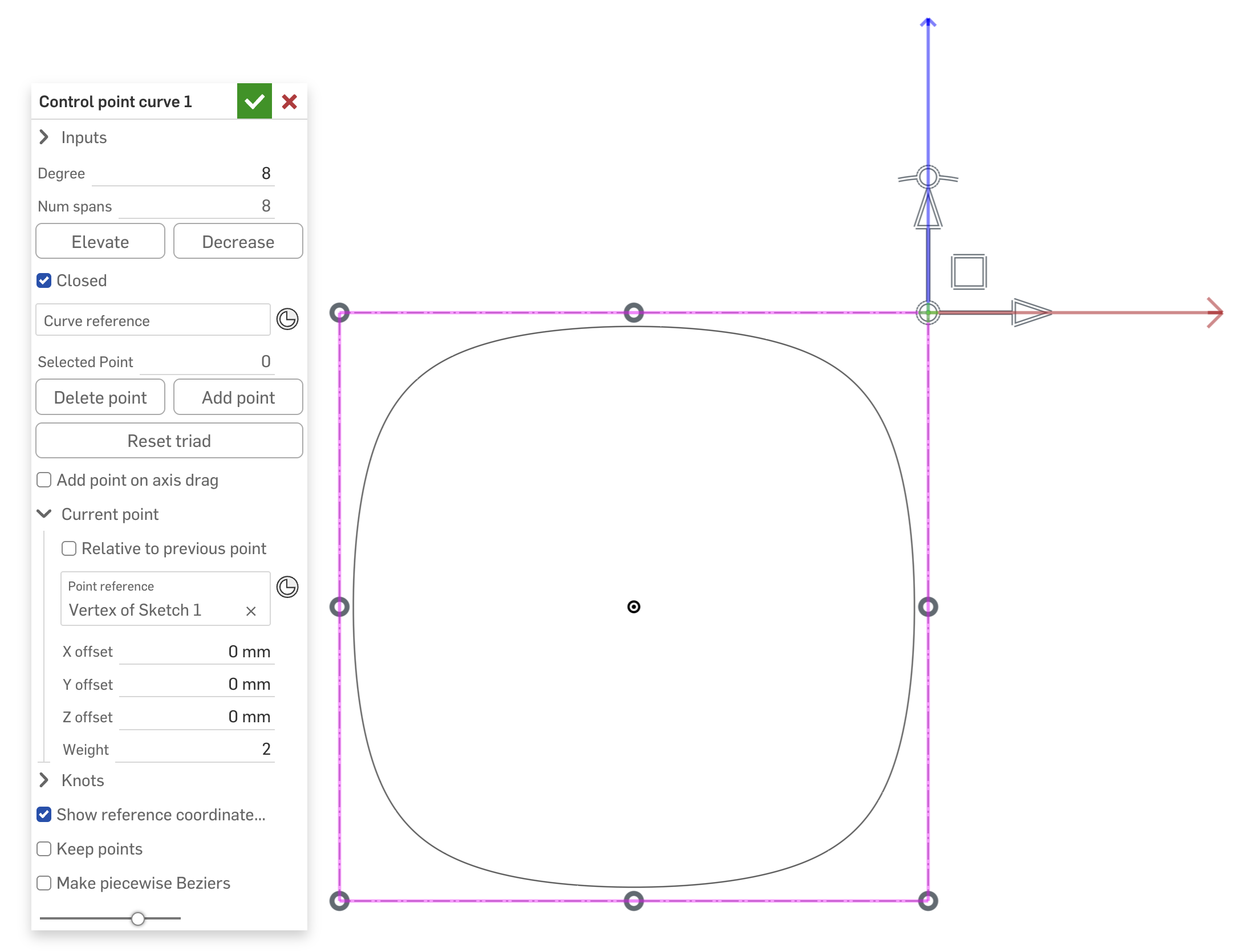
The curvature combs are pristine for this…
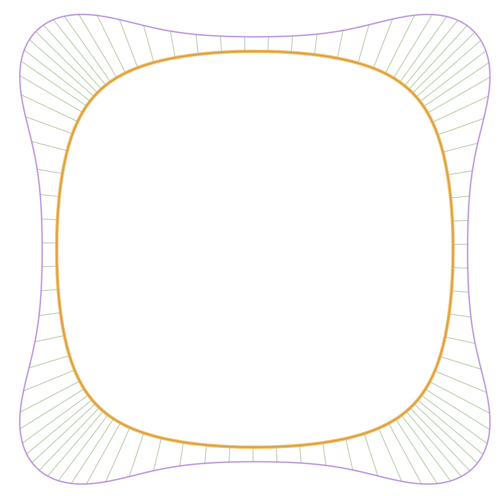
There is another part studio with one corner created from a Control point spline (degree 2, with the middle CP set to weighting of 2). This is then mirrored twice.
In both cases just play with the Weight parameter to get the desired effect.
