Welcome to the Onshape forum! Ask questions and join in the discussions about everything Onshape.
First time visiting? Here are some places to start:- Looking for a certain topic? Check out the categories filter or use Search (upper right).
- Need support? Ask a question to our Community Support category.
- Please submit support tickets for bugs but you can request improvements in the Product Feedback category.
- Be respectful, on topic and if you see a problem, Flag it.
If you would like to contact our Community Manager personally, feel free to send a private message or an email.
Best Of
Re: Improvements to Onshape - September 19th, 2025
Sometimes coming into the office on Monday is a great thing! Assembly mirror is amazing! And by the looks of it, Onshape has indeed nailed the implementation. Looks to have loads of control in all the right places. 🤩. Hoping for mirrored sheet metal; to be able to include there flat pattern as well. 🤨

Re: Looking for some help with release packages in the API
Hi Jon, not sure if you still need this, but for anyone else coming across this post:
wfid here is the workflowId.
You can get this using /GET https://cad.onshape.com/api/companies/{yourcompanyid}/policies
Look for the key releaseWorkflowId

Re: Pattern on a sphere
I see what you mean, just adjust your sketch profile in that area to have more depth. \__/


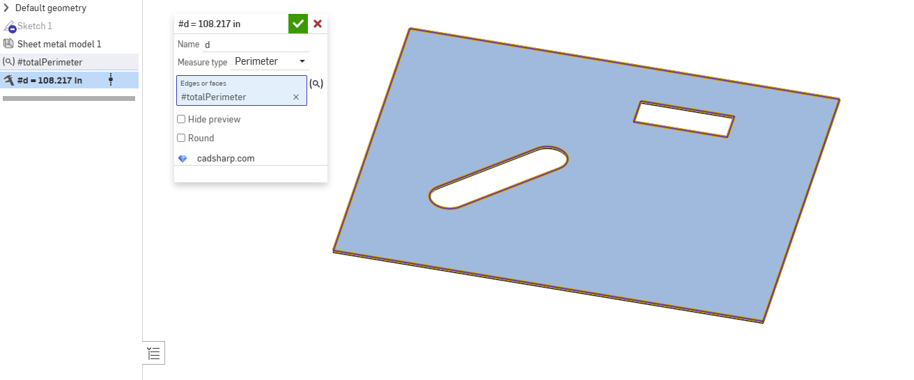
Re: How to Calculate laser cutting length ?
Or for $10 you can get a copy from fs.place that shows a toolpath and drops some estimates into a table for you.

Printable Fillets
I made a custom feature to easily implement printable fillets, aka fillets that have a slightly sharper transition to the faces than a standard tangential fillet, to enable more accurate 3D printing. This is my first attempt at something like this, and constructive feedback is very welcome. https://cad.onshape.com/documents/643eceb32d9650249dd16a3e/w/78be64c6d1a48ea091dd93cb/e/16321f49c31ef6b8038a0f53

Re: How to Calculate laser cutting length ?
.
You could use the new Query Variable paired with
 Measure Value by @Konst_Sh to dynamically get this measurement:
Re: Improvements to Onshape - September 19th, 2025
Another huge update! Assembly Mirror looks great, can't wait to try it out
It would be better if the Assembly Mirror maintained Active Sheet-metal
