Welcome to the Onshape forum! Ask questions and join in the discussions about everything Onshape.
First time visiting? Here are some places to start:- Looking for a certain topic? Check out the categories filter or use Search (upper right).
- Need support? Ask a question to our Community Support category.
- Please submit support tickets for bugs but you can request improvements in the Product Feedback category.
- Be respectful, on topic and if you see a problem, Flag it.
If you would like to contact our Community Manager personally, feel free to send a private message or an email.
Best Of
Re: Configure Part Name Feature?
@john_mccullough That is unfortunately a current limitation of all custom features due to the order the code regenerates in. The feature list generates first, naming the part, then the user-speficied part properties regenerate, overwriting the feature. Right now the Reset All button is the only way, but I'd love to have the ability to reset just one property in the future.

Re: Emojis within feature notifications 😀☠️💣
Windows key + period key 💯💯💯🔥🤘
It has quick insert ASCII faces too so I can comment on my team's drawings with this face but no helpful dialogue ಠ_ಠ

laser cut boat hull


 How do I make a boat hull, and eventually laser cut it? I want to make it in strips on the side, using laminate/veneer (not sure of material yet). This is prototype, actual one will be made with 3 mm wood

Re: Free Onshape Projects with instruction sheets, drawings and step by step videos available
Hi, I have just updated all of the projects and instruction for 2025. I have added video instruction for reading engineering drawings and working with design intent as well as modeling parts and assemblies in Onshape. Also, directing students to check the accuracy of their modeling using mass properties and make revisions to check the design intent was met. Check these updates as well as a new website for accessing them for the comming school year. https://www.cadvideotutor.com/

Re: Free Onshape Projects with instruction sheets, drawings and step by step videos available
Wow, John! These look great! I might have to move from PTC to John Granger's CVT. Thank you so much!
If you don't mind, I would like to include your website in a tutorial GPT I pieced together for Onshape. I'm using all the training matieral from PTC as well for the GPT. It's kind of like an Onshape assistant that works with you to make designs. Just tell it what you want and it will provide text based instructions for you to build a project. Its also instructed to give credit for any source it uses, including yours.
Here is the tutorial GPT.

Emojis within feature notifications 😀☠️💣
Nothing new, but I would like to point out that we can put emoji within feature warnings!

.

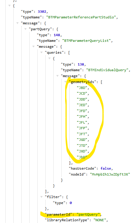
Re: Onshape API: How to get the source Part (Part ID like #JFD) of a Derived part?
You can get the source part id from the /partstudios/…./features endpoint.
The parameter "partStudio" → partQuery → Queries → geometry IDs
The caveat is that it also depends on what version of the api endpoint you use.
for example:
doing /api/v12/partstudios/…/features won't give it to you (Gives a compressed query)
but /api/v1/partstudios/…/features will give it to you (gives a list of geometry ids).
Some API versions are slightly different in what information they give you. Sometimes you need to try a couple different ones to find the one that works for your specific needs.