Welcome to the Onshape forum! Ask questions and join in the discussions about everything Onshape.
First time visiting? Here are some places to start:- Looking for a certain topic? Check out the categories filter or use Search (upper right).
- Need support? Ask a question to our Community Support category.
- Please submit support tickets for bugs but you can request improvements in the Product Feedback category.
- Be respectful, on topic and if you see a problem, Flag it.
If you would like to contact our Community Manager personally, feel free to send a private message or an email.
How would you create this curve feature?

I'm trying to recreate this bubble wand (but make it larger).
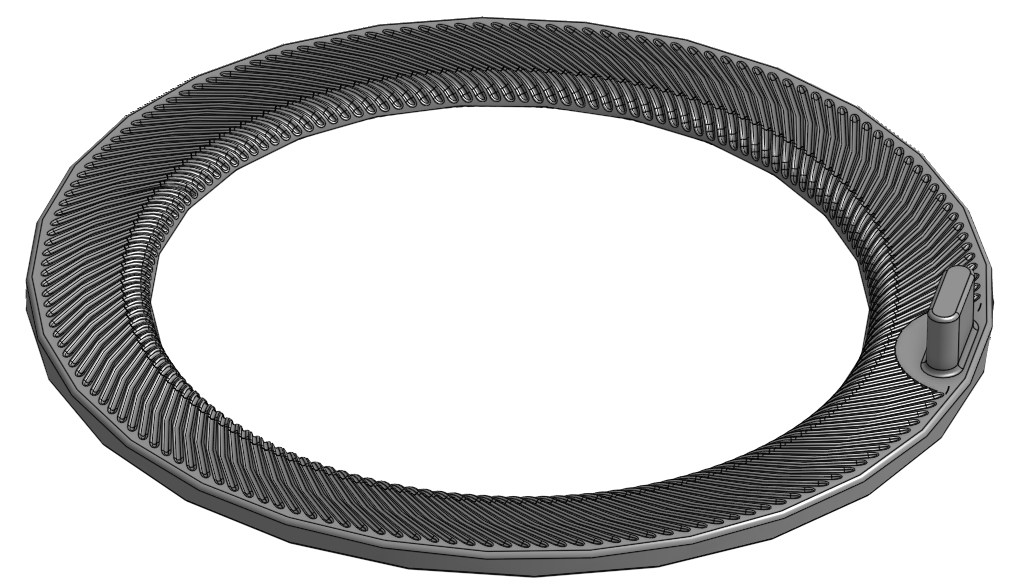
There are these channels that I'm having trouble recreating…
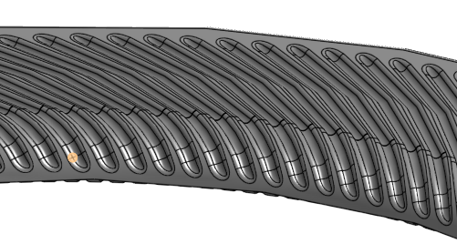
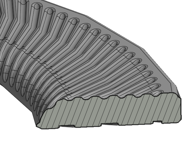
I was able to figure out that the feature is a swept cut of an arc that's projected down onto the faces below, however all my attempts to project the last portion of the arc down onto the face are failing. Pls help.
Best Answer
-
Hello. One method was used in this document.
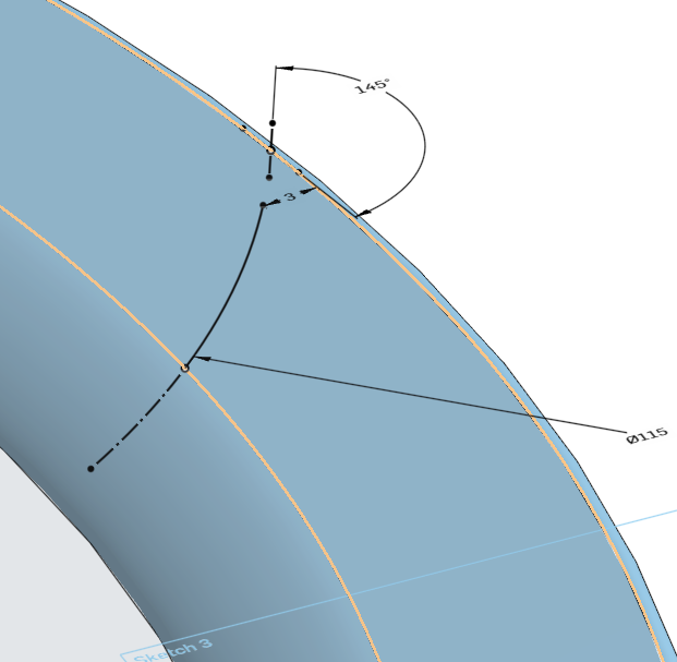
First step after creating the toroid was to create a mate connector and to assign variables of angle and distance to it. The purpose of the mate connector is for a Split of the toroid. After the split, a sketch was created on the face of part 2 created by the split and elements of the edges of the face of the part were 'captured' with the Use tool to become the path for a sweep. The profile of the sweep was created on the flat bottom of the part 2. Then the sweep and a circular pattern of the sweep feature. A boolean is used to rejoin the parts created by the split.
A plane or surface could have been for the split, but a mate connector is, in my opinion, ideal because of its versatility.
- Scotty
0
Answers
-
Hello. One method was used in this document.
First step after creating the toroid was to create a mate connector and to assign variables of angle and distance to it. The purpose of the mate connector is for a Split of the toroid. After the split, a sketch was created on the face of part 2 created by the split and elements of the edges of the face of the part were 'captured' with the Use tool to become the path for a sweep. The profile of the sweep was created on the flat bottom of the part 2. Then the sweep and a circular pattern of the sweep feature. A boolean is used to rejoin the parts created by the split.
A plane or surface could have been for the split, but a mate connector is, in my opinion, ideal because of its versatility.
- Scotty
0 -
Hi Scotty, ah the profile of the cut is an arc, not a straight line/plane, so I went with a surface instead of the mate connector. But yes, cutting the part did the trick, Thanks!
Any idea how I would make the ends rounded like this?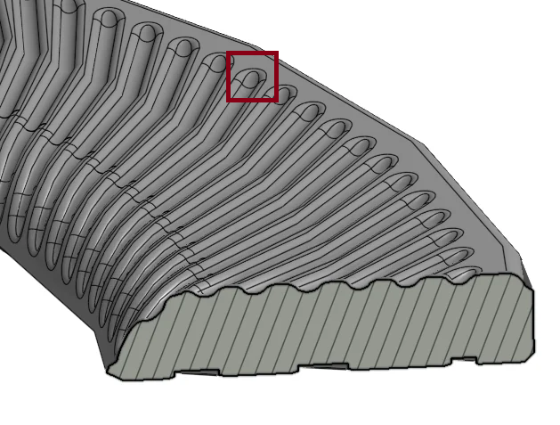
I was able to get it this far…
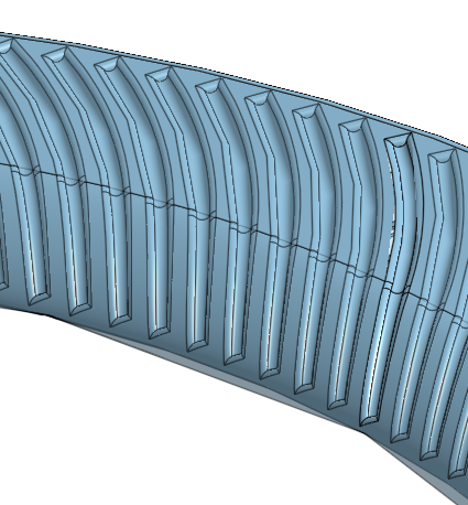
At this point I think it will be functional for what it's meant to do, but just asking out of curiosity.
Thanks!
0 -
(deleting because posted twice)
0 -
Take a look at the 'rounded ends' part studio in the updated document I posted earlier. Something weird going on there that I don't understand. The rounded ends of some of the grooves are not being rounded and there is a pattern to it. I made a variable for the instances of the circular patterns. Changing that value does not make any difference except perhaps for which grooves.
I hope another forum member can explain that; I'm kinda curious.
- Scotty
0