Welcome to the Onshape forum! Ask questions and join in the discussions about everything Onshape.
First time visiting? Here are some places to start:- Looking for a certain topic? Check out the categories filter or use Search (upper right).
- Need support? Ask a question to our Community Support category.
- Please submit support tickets for bugs but you can request improvements in the Product Feedback category.
- Be respectful, on topic and if you see a problem, Flag it.
If you would like to contact our Community Manager personally, feel free to send a private message or an email.
3D Scan Alignment

Hi all,
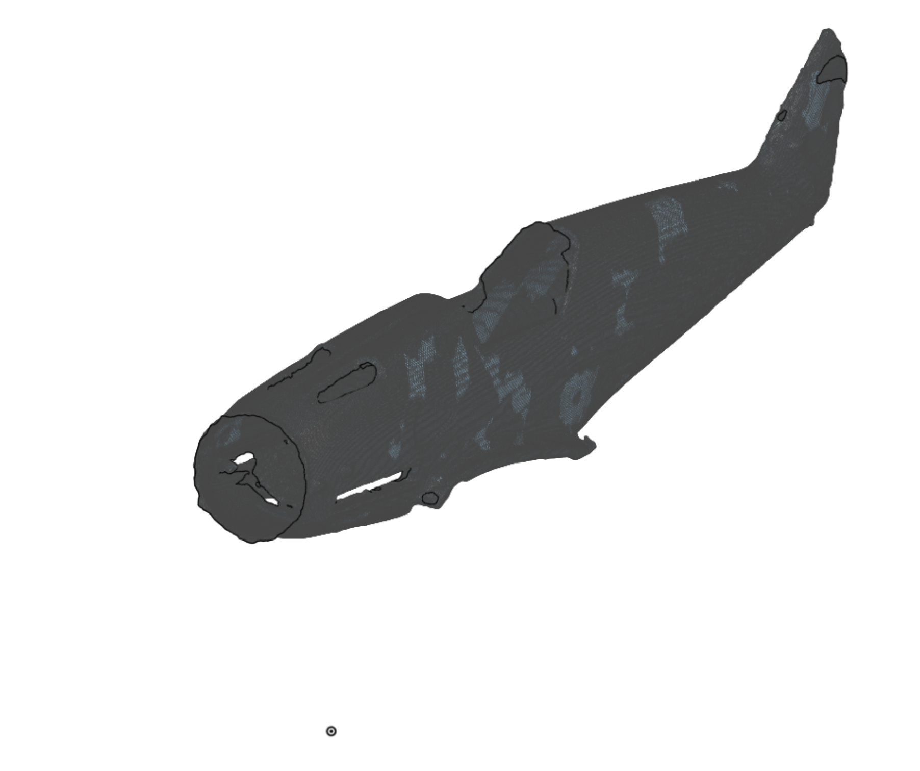
I have a 3D scan of a 1/48 scale model aircraft fuselage - image attached. This is my first time working with a mesh.
I want to split it vertically into two halves along its length and reorient it such that the nose is centred on the origin and the centre split faces are on the Right plane with its length running along the X axis.
I've experimented with mate connectors and transforms but haven't managed to find the right combinations.
Any help appreciated.
Thank you.
Best Answer
-
ah, its not a solid mesh its a surface mesh. best approach will be to create a drawing on your split plane then manually move it via Transform by mate connectors, like this:
https://cad.onshape.com/documents/3e0c82fc4078a8333619e4eb/w/8507c39a973ce4fadea88b3c/e/e6951b52b9c285b8ae8a1…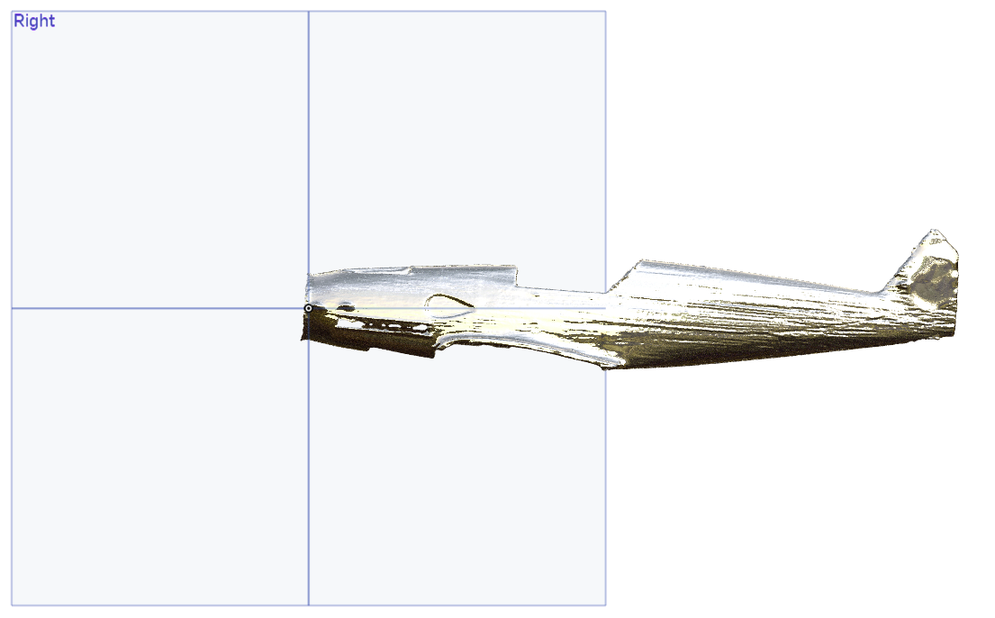
.
RENDERCAD
rendercad.ai - Photorealistic product rendering.
▚▞▚▞▚▞▚▞▚
________________________________________________________________________0

Answers
-
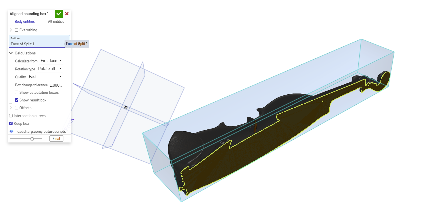
There are other ways to do this, but here is my workflow (Michael's Violin Scan). It requires this custom feature: Aligned Bounding Box.
3 point plane > split > aligned bounding box > transform
.
RENDERCAD
rendercad.ai - Photorealistic product rendering.
▚▞▚▞▚▞▚▞▚
________________________________________________________________________0 -
Thank you.
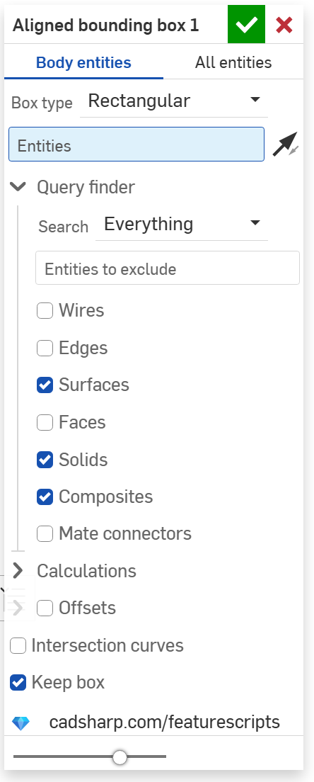
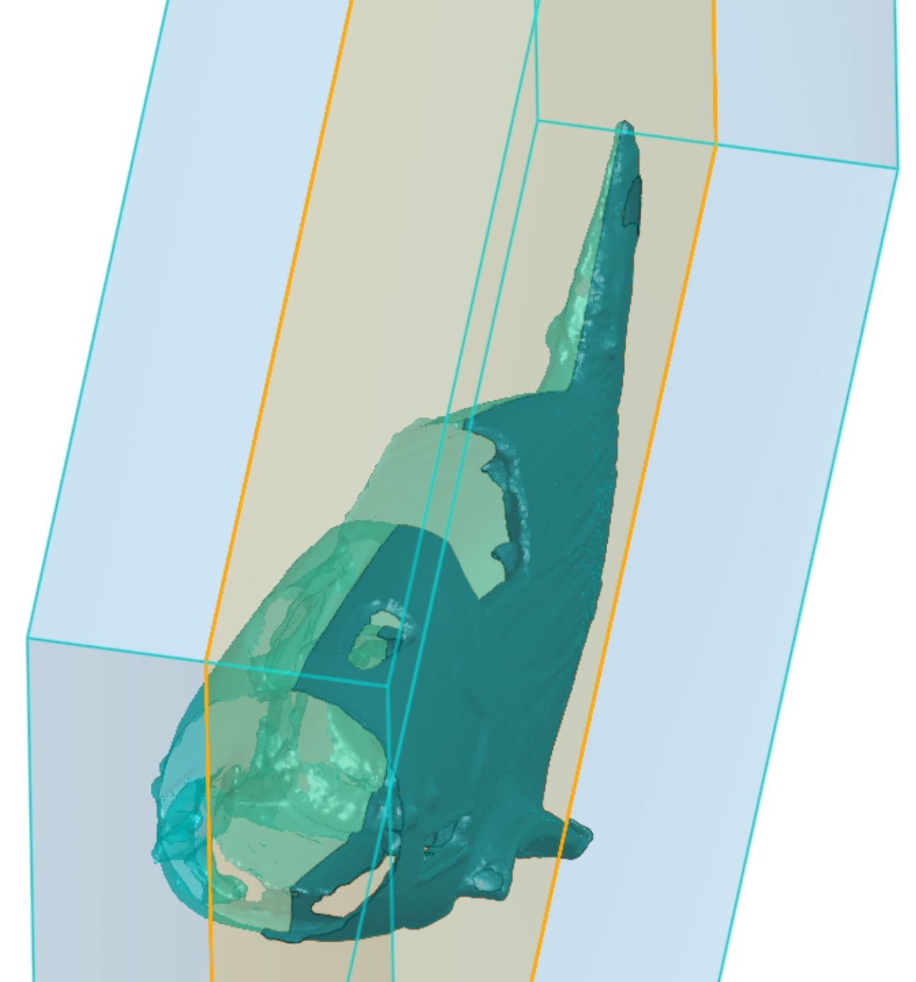
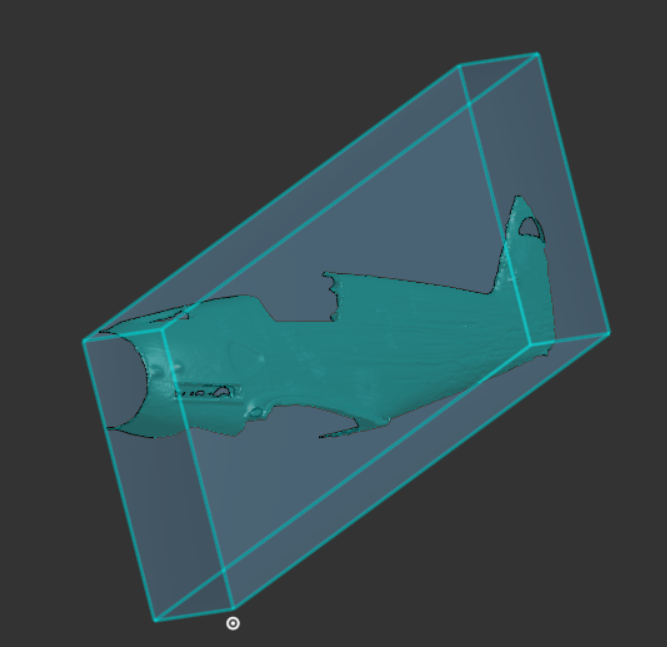
I've split my scan into two parts but when I apply the Aligned Bounding Box I cannot select any entities other than the plane I used for splitting so the boundary is calculated to cover both fuselage halves..I'm sure I'm missing something!
Thank you.
 0
0 -
By deleting the unwanted fuselage half the bounding box does as I need - is it the intended behaviour that there should be only one candidate part / surface?
 0
0 -
Toggle off the query finder by clicking the toggle arrow (right next to the "Entities").
Here are my settings:- Select the face that was split.
- Calculation from "First face"
- Rotate all
RENDERCAD
rendercad.ai - Photorealistic product rendering.
▚▞▚▞▚▞▚▞▚
________________________________________________________________________2 -
Thank you but I still don't seem able to select the surface, I can select mesh points and planes.
0 -
are you able to share a link to your document? I'll take a look.
RENDERCAD
rendercad.ai - Photorealistic product rendering.
▚▞▚▞▚▞▚▞▚
________________________________________________________________________0 -
Here's the link:
https://cad.onshape.com/documents/50b2ead4ed7c48b464b41fb3/w/5e7d095bdc40de2bbde7ee76/e/cfc8aa9a5b5965cb58bff894
The scan is rough but it's all I have at present.0 -
ah, its not a solid mesh its a surface mesh. best approach will be to create a drawing on your split plane then manually move it via Transform by mate connectors, like this:
https://cad.onshape.com/documents/3e0c82fc4078a8333619e4eb/w/8507c39a973ce4fadea88b3c/e/e6951b52b9c285b8ae8a1…
.
RENDERCAD
rendercad.ai - Photorealistic product rendering.
▚▞▚▞▚▞▚▞▚
________________________________________________________________________0 -
Thank you, that works well!
0