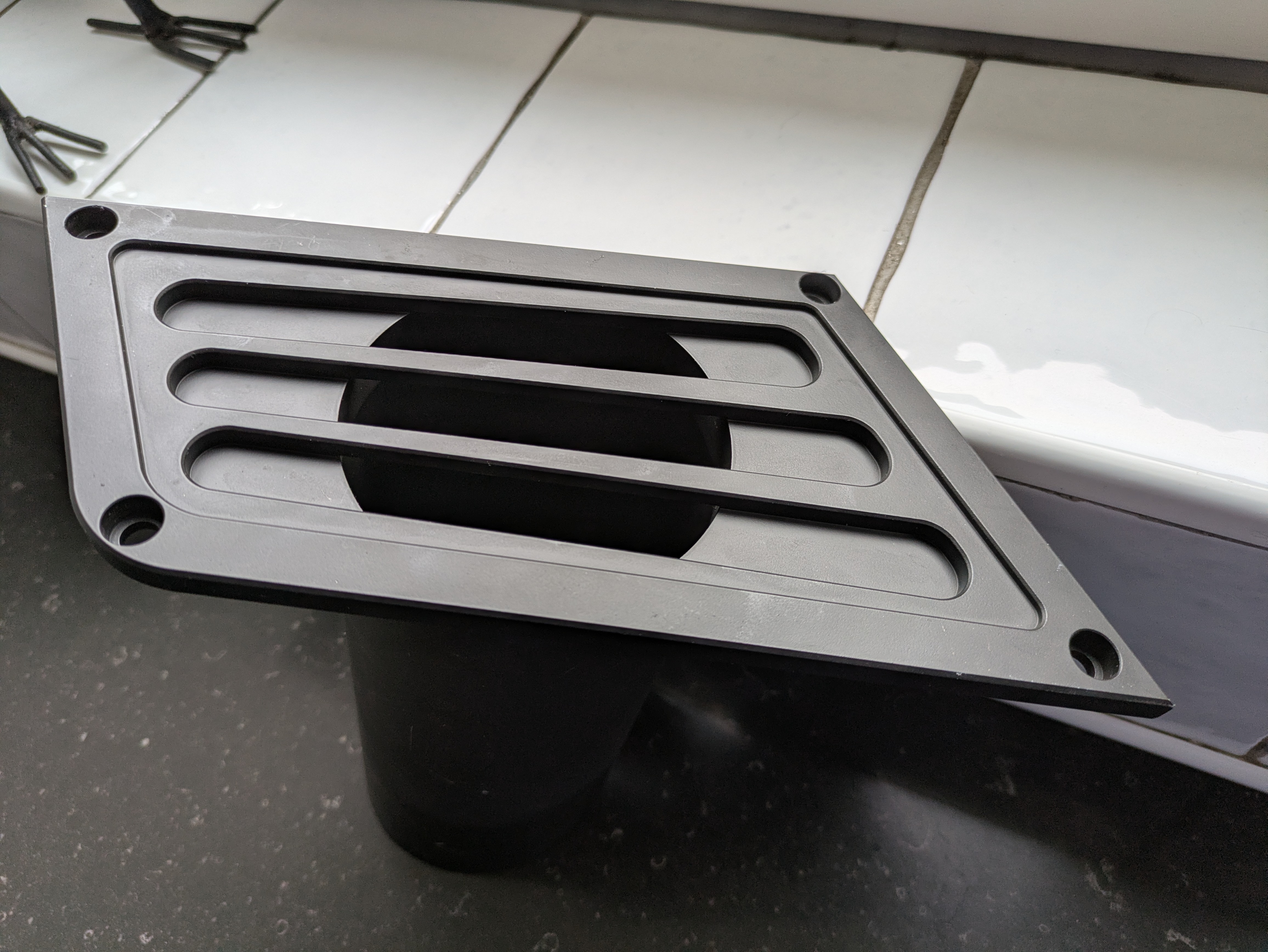
need help creating object with differnt width/depth on all 4 corners

Hi All,
just started with onshape/cad drawing and need some help.
I needed to make a spacer for for a turbo airintake , and managed to make the right shape, but I just can´t get the depht/width right.
The object should have a different depht on all 4 corners, can anybody help?
Answers
-
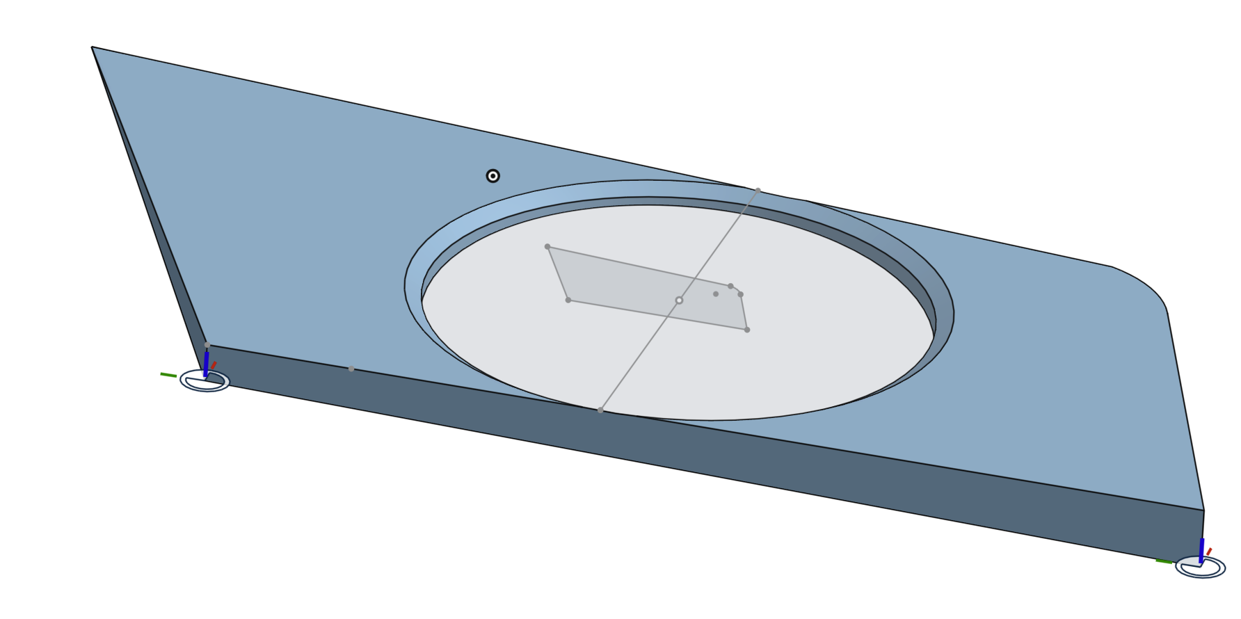
You could put mate connectors at the correct depth at 3 of the corners. Then make a plane and split the part.
 0
-
Hey Jack. The top surface is curved? The bottom surface is flat? - Scotty
0 -
thanks for the help Mat, but I just started with whole 3d/onshape and learning curve is quit steep.
could you elaberate a bit more, I managed to make a new object whitout the imported image file in the back.
where should I start with setting the mate connecters? edit sketch1 or the extrude?
both top and bottom surface have a curve in one corner, are the same.
0 -
https://cad.onshape.com/documents/4f30ffdc33ad03f6937b97e7/w/a98359b9abee973c351c7965/e/5ea017cd8215357ff4528751
0 -
-
Thanks for the help, this is what I meant.
but I have to learn more about using the mate connectors.
the base depth at the curved corner should be 20.5 mm , then mate connector 1 should have 8mm depht,
mate connector 2 should have 2,5mm depht, and
mate connector 3 should have 15mm depht.
But when I set base depth with extrude, it doesn´t correspond with actual depht when I use dimension tool to check measures.
Have to read more manuals I quess.
0 -
I'm lost what you are trying to do. Are you trying to make an angled spacer to go between the plastic commercial part you shared in post 1 (as a picture), and a piece on your car?
Off topic, why did you use a transform to scale your part? Why didn't you draw it initially to the size needed?
0 -
Yes I´m trying to make an angled spacer .
I scaled my part cause I initialy started with an image/scan of the outside lines of the part , and then draw over the lines to get the exact angles of the part.
0