Welcome to the Onshape forum! Ask questions and join in the discussions about everything Onshape.
First time visiting? Here are some places to start:- Looking for a certain topic? Check out the categories filter or use Search (upper right).
- Need support? Ask a question to our Community Support category.
- Please submit support tickets for bugs but you can request improvements in the Product Feedback category.
- Be respectful, on topic and if you see a problem, Flag it.
If you would like to contact our Community Manager personally, feel free to send a private message or an email.
First attempt at Analysis - need help

My first play with the Analysis feature of OnShape. I have a simple structure which is a composite beam consisting of two elements (upper and lower) having different properties, fastened together with bolts. The load is applied to the lower element, but only the upper element is supported at each end.
I am ultimately wanting to estimate the stresses in the connecting bolts. As a start, I have used fixed mates at each bolt point, and supported the ends in a way that permits rotation and translation. I have set the Connectivity Method to be only via Mates. The overall deflection is broadly what I would predict from a simple uniform beam analysis, but where I would expect to see stress points at each of the connecting mates, I see just overall uniformly low-stress regions across almost the entirety of the composite structure.
It's my very first attempt (I have watched a number of the introductory videos) so I am guessing that I am making some sort of rookie mistake. I would greatly appreciate any pointers to what that might be.
This is the link to the model:
https://cad.onshape.com/documents/2edb0b04dbc05f310e8e0e1a/w/1ad29dcbefda8860e378858d/e/2232a517725c2700ac63f4c3?renderMode=0&uiState=6a8e7a11f776b43fc09e153a
Answers
-
You've got a simply supported beam with your rotate & slide connection which is really good.
I agree and believe your beam faces are bonded and would expect to see higher stresses at the bolt connections.
You don't need to declare these mate connectors, they're already part of the fasten joint.
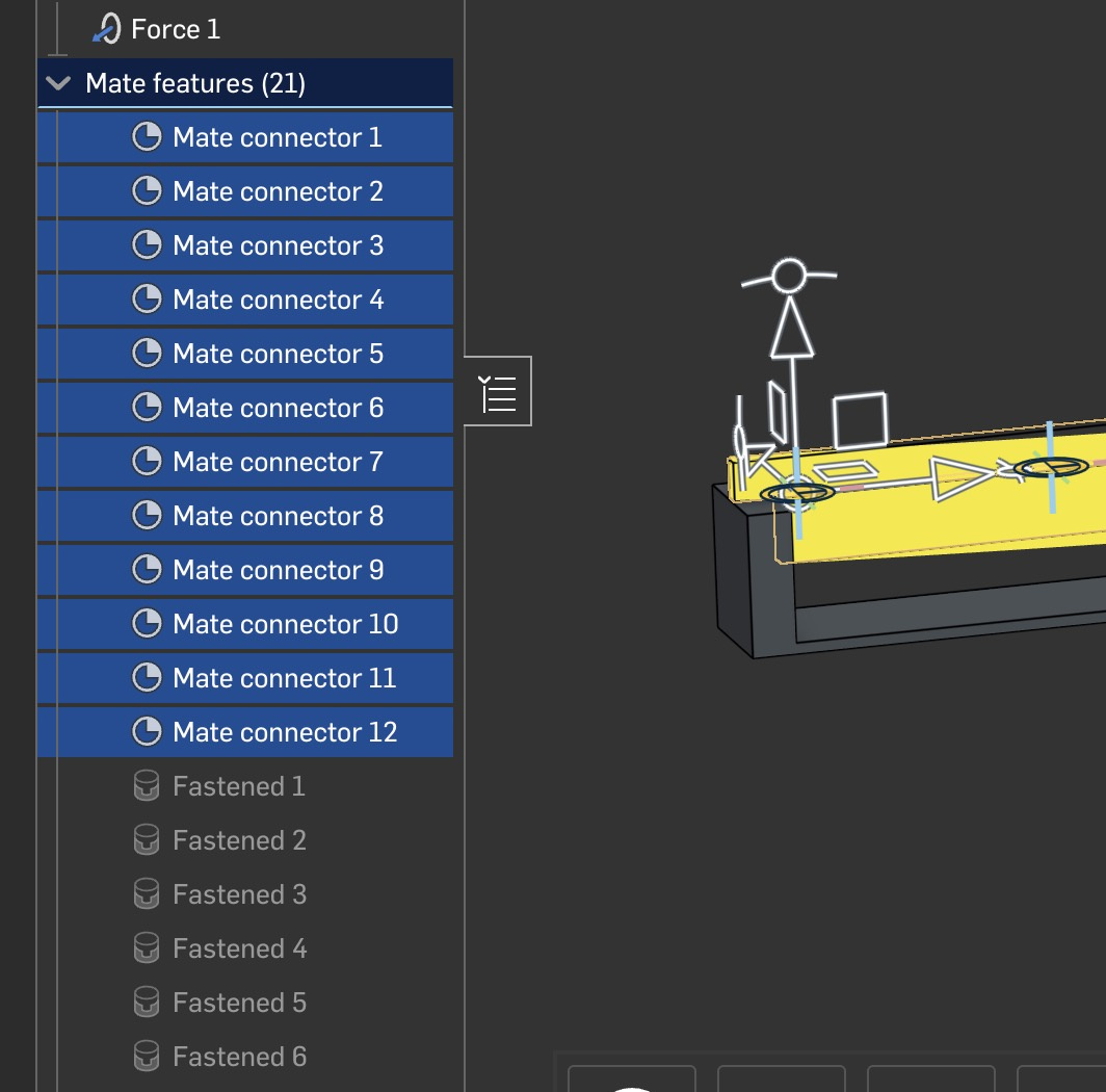
The problem is that I don't know what faces fastened1 is referencing. I believe the 2 faces of the beams are bonded.
One issue with Onshape analysis is that edges and vertices are not used as constraint references. Now you can argue that's wrong. It's point loading and will distort your answer. I believe that fastened/mate connectors are referencing the beams face and the 2 face are indeed bonded.
I'd split the faces and bond the split faces
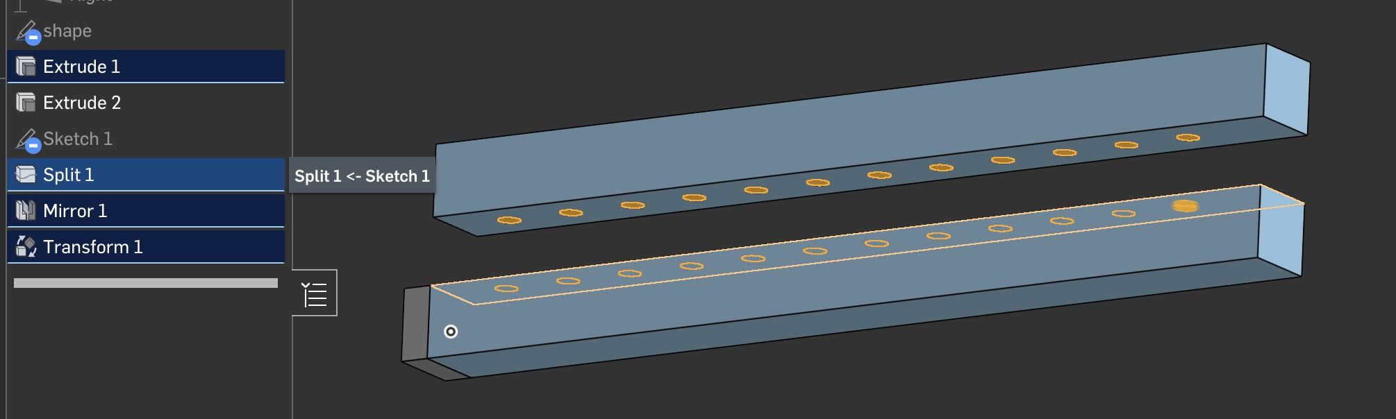
Now I know what's being constrained to what.
2nd and most important, bolted connections are difficult. 2 holes and a bolt will drive you crazy. First off, we need contacts which we don't have. But don't worry, they're not accurate either and they take a long time to solve. If you want to get picky, a bolted connection is a non-linear contact problem worth weeks of time to do correctly.
You should really splitting the contact area on each beam and constrain them together.
Also, since you're starting, and you're doing very well, remember that you can't constrain edges or vertices and you always need faces. You're going to start splitting a lot of faces to control your constraints properly.
Also, to be picky, I believe your analysis isn't constrained in the Y direction.
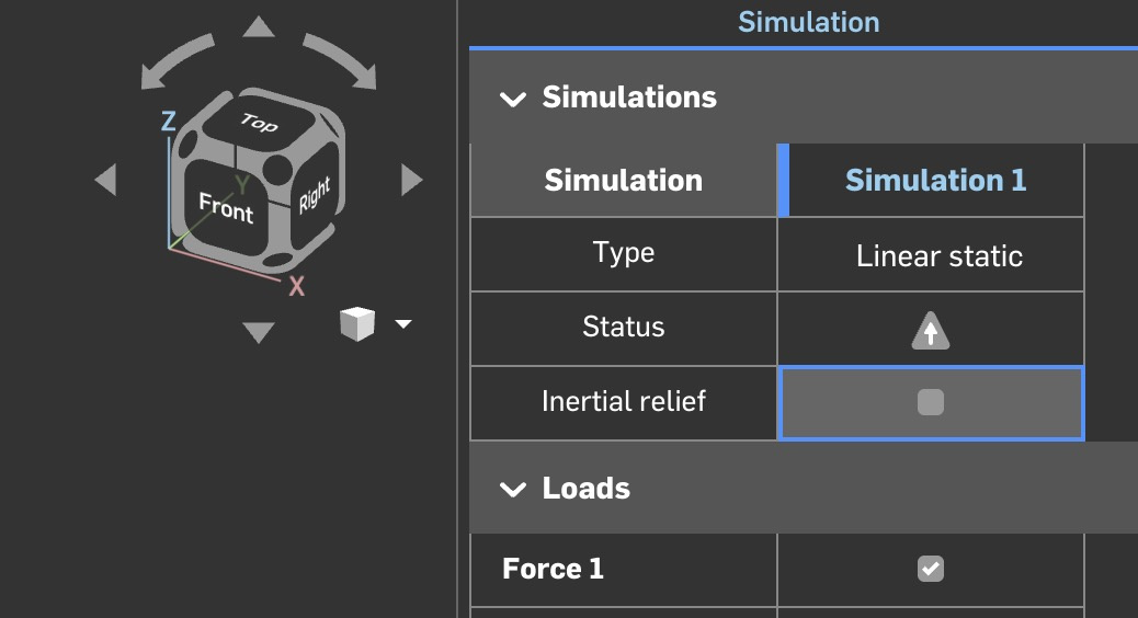
Your analysis could start failing due to mathematical round off errors. Sum Y forces might not equal 0 and therefore your model should start to accelerate which isn't allowed. You should turn inertial relief on. It balances out the mathematical errors when summing the forces. It's something you shouldn't have to think about and for the longest you didn't have to, but, they added a button. For most cases, it should be on.
Sorry, this is long winded and I need another cup of coffee. You're doing really well. Keep it up and show me more.
0 -
There is no need to guess, you can confirm the beams are bonded using "show connections":
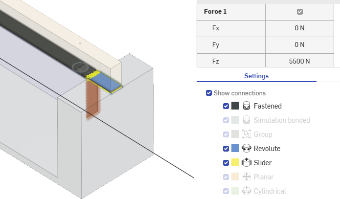
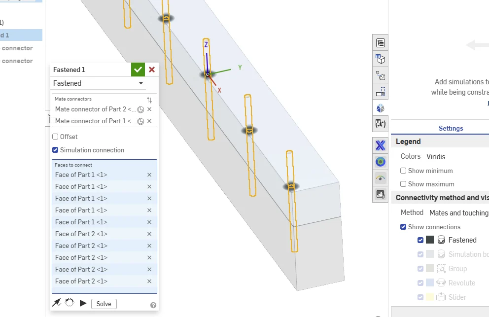
I think all you need to do is use a single fasten mate between the two beams and use the "simulation connection" checkbox to define the "connected" faces: you should just be able to pick the inside faces of the holes and use "show connections" again to confirm.
EDIT, like this: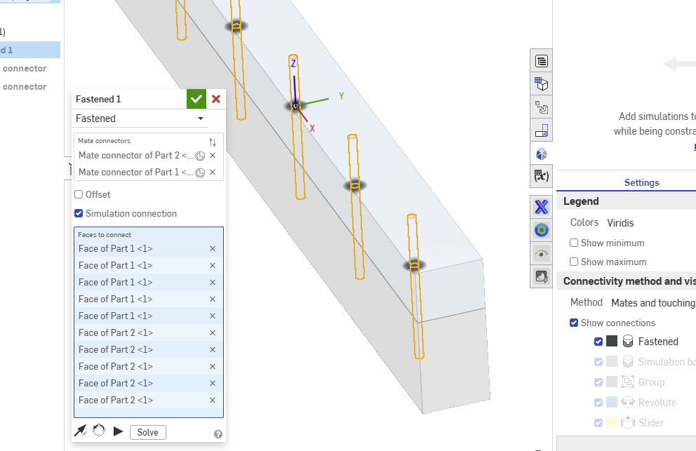 0
0 -
@eric_pesty I like that, it's like driving a pin between the 2 beams. I'm just wondering if that's creating a rigid body between the 2 parts?
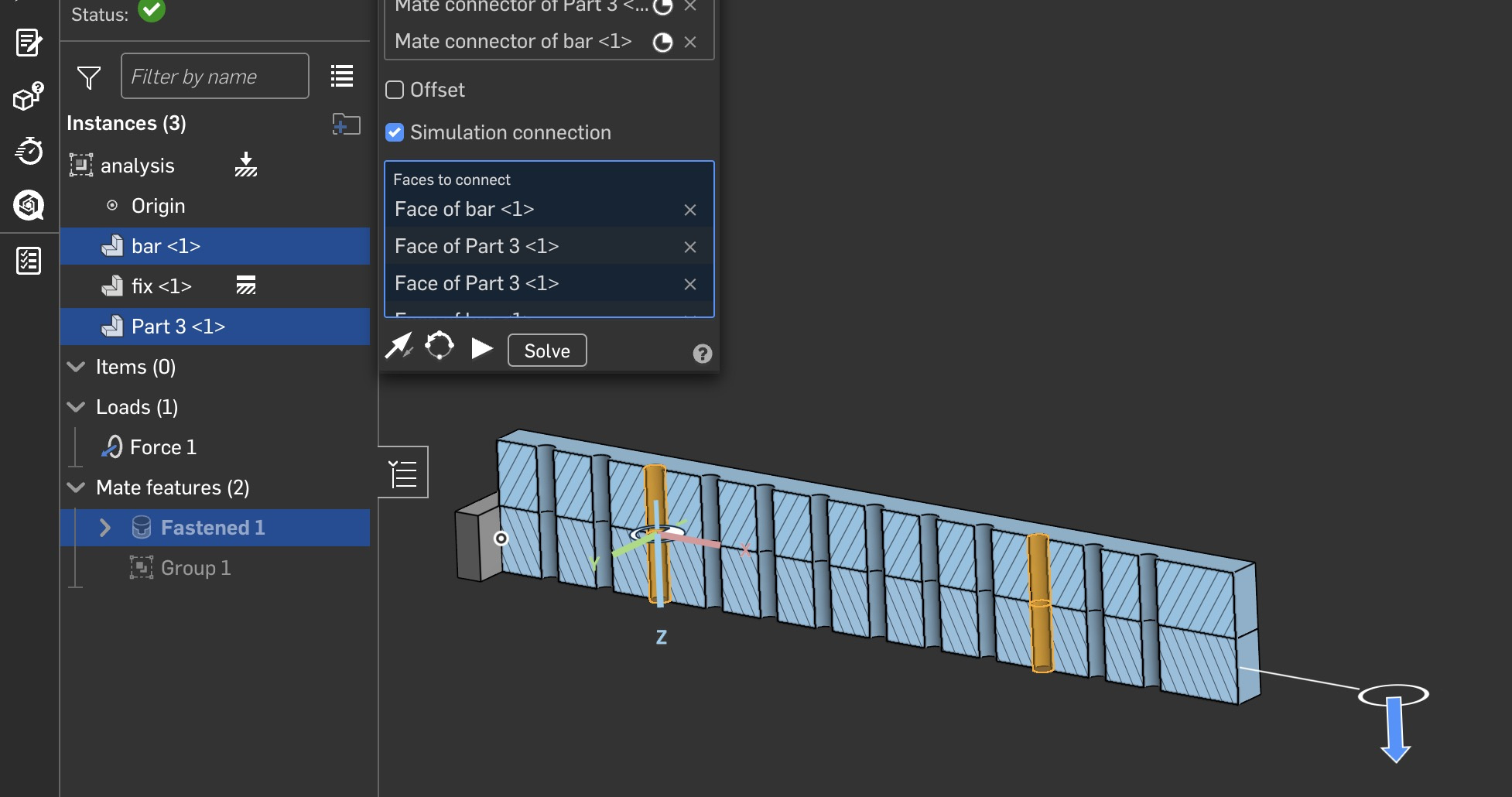
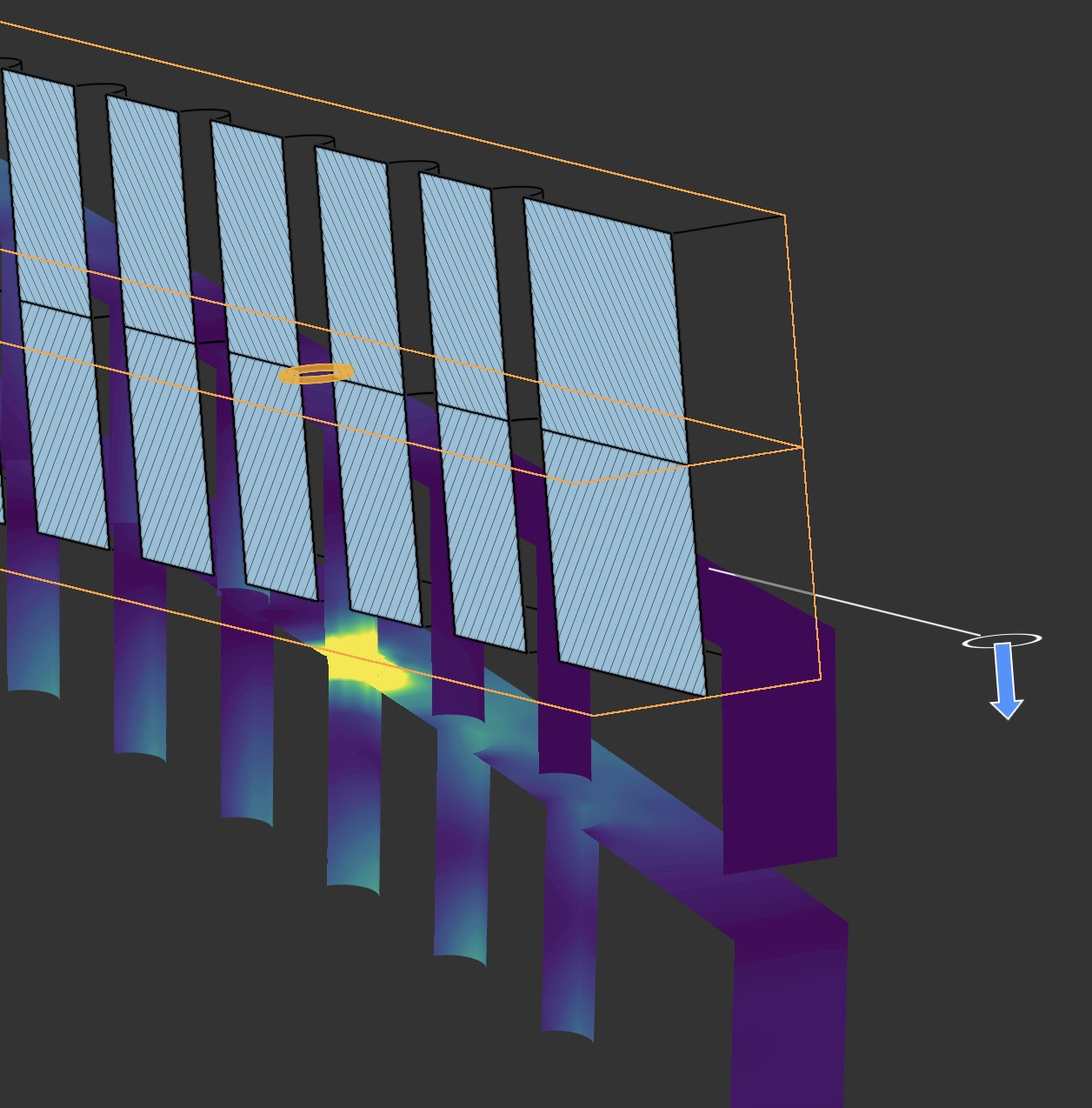
Nope, it's not a rigid body, looks like it's an edge connection. I guess you can create edge connections. I didn't know that.
To confirm the edge connection, I added a pin to the adjacent hole.
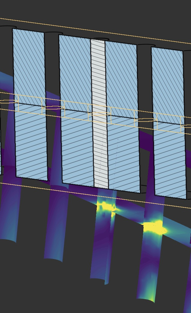
The pin cleans up the stresses, confirming that it's probably an edge connection.
0 -
@billy2,
I'm not sure what it does in the background but it seems like the connections "taper" to some extent. I don't think it's quite like an edge to edge connection, because it is based on face selections and doesn't necessarily stop at edges.It shows up in the "show connections" as different densities:
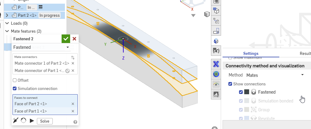 0
0 -
Thanks, guys…that's a lot for me to digest (given my newness to all this). I had thought about separating the beams and providing explicit contact bonds, so I'll go ahead and try that. And of course the reminder that you can display the connections is very helpful. I'm going to explore a bit more and see where this leads. It's a (big) learning exercise for me.
0 -
Despite the fact that I have defined the connections as "mates only", the whole region between the beam faces shows as black - fastened. So I split the faces between the two beams and made a small explicit bonding area in the region of the previous connections. The whole region still shows as fastened even though there is an air gap (2mm) between them. Obviously, "fastened" means something here that is not intuitive to me. I opened the air gap to 5mm, and the black shading is fainter, so I guess I'm not understanding what the coloration represents.
0 -
Sorry guys, I met Dr. Weingarten at comdex (1990's) a long time ago and have been friends for a long time. He wrote cosmos that ran in 640k of ram and I've been playing with it for a long time. This program is similar to this one except Onshape has taken all the buttons and settings and removed them. This is a good thing. I'm trying to figure out what's it's doing. I like this solver a lot and how it's setup.
I haven't done a bolted connection yet, but have wanted to. They're hard to do and get right. I'm going to tear into this stuff and see if I can't figure it out. I want answers to all these questions. FEA isn't that difficult.
0 -
This is likely because it defaults to "bonding" touching faces, you have to change the Connectivity method to "Mates" here:
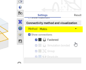
I meant to mention that in my earlier post, sorry about that… Hopefully changing this will help…
0 -
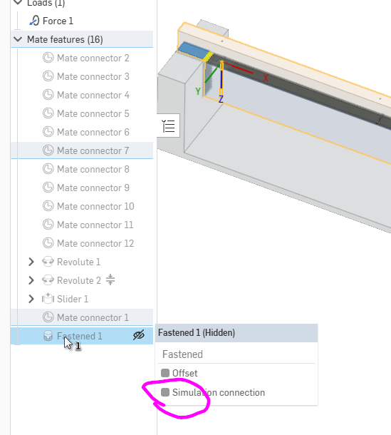
Also, I looked at your doc and I don't see the "simulation connection" box checked in your fastened mate, this is where you can spell out the contact faces to "fasten".
 0
0 -
@eric_pesty Thanks. I had definitely selected "mates" as the connectivity method. I will explore the "simulation Connection" thing but could you elaborate a little more on what this does?
Thanks
0 -
I typically use the default "mates and touching faces". I'm finding this disturbing because it'll fix things that are close and not touching.
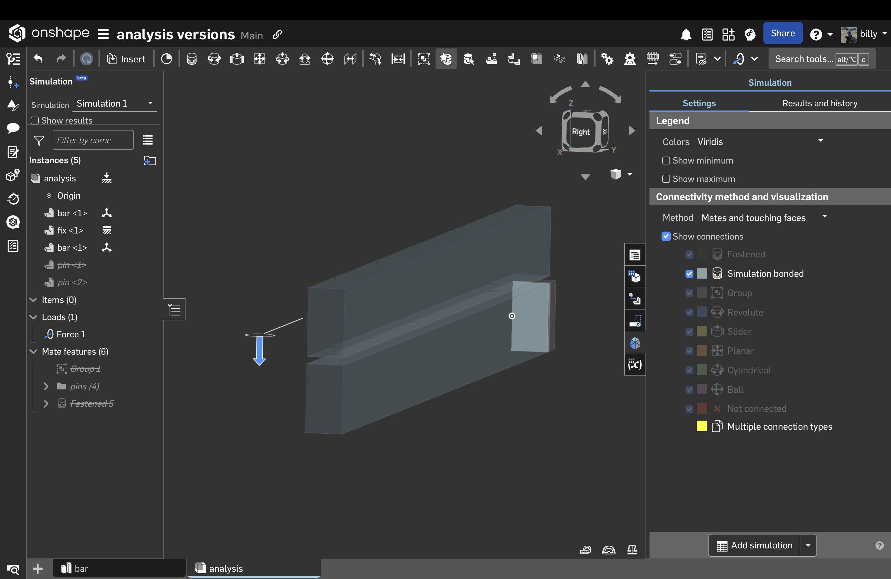
If you're analyzing a bolted connect you have to switched to "mates" because touching means those things that are close. I moved the top beam up to 4mm separation before it stopped fixing to 2 beams together. That's a really bizarre behaviour.
On a positive note, you can turn on show connections before running an analysis to see what it's doing and how it's constraining the model. It's takes a while to figure out what it all means but it's telling you what it's doing.
0 -
That lets you manually define the faces the "fasten" is applied to and that's how I got this image. I clicked the checkbox and that adds the selection box in which I picked all the cylindrical hole faces:
 0
0 -
@eric_pesty I'm really glad I took the time to understand show connections dialog. I've had problems in the past that could have been solved by understanding this dialog box. Thanks!
I added a planar mate between the beams which over rode that bazarre touching mate. I only have 1 mate in my analysis with the other mate being designed by touching the fixed block.
My bolted connection a little different than yours, sorry. I wanted contact between the 2 beam but I don't want shear. Engineering wise: the beams strength is one beam height cubed and then x 2, it's not 2 beam height cubed
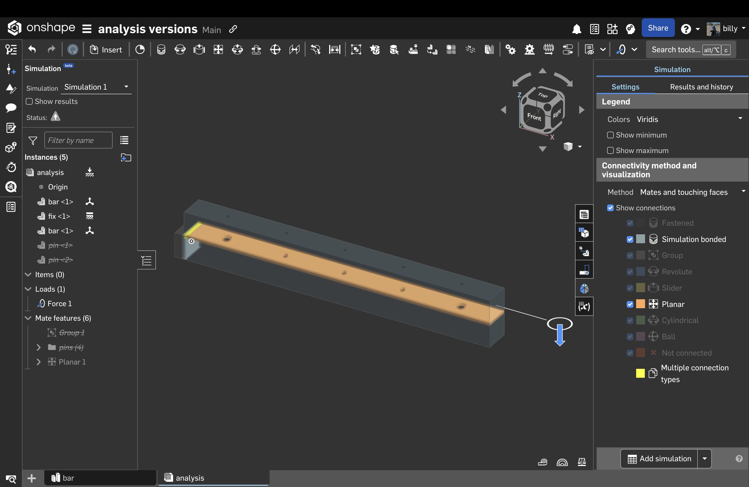
If you look below, the bottom beam is longer than the top because they're slipping.
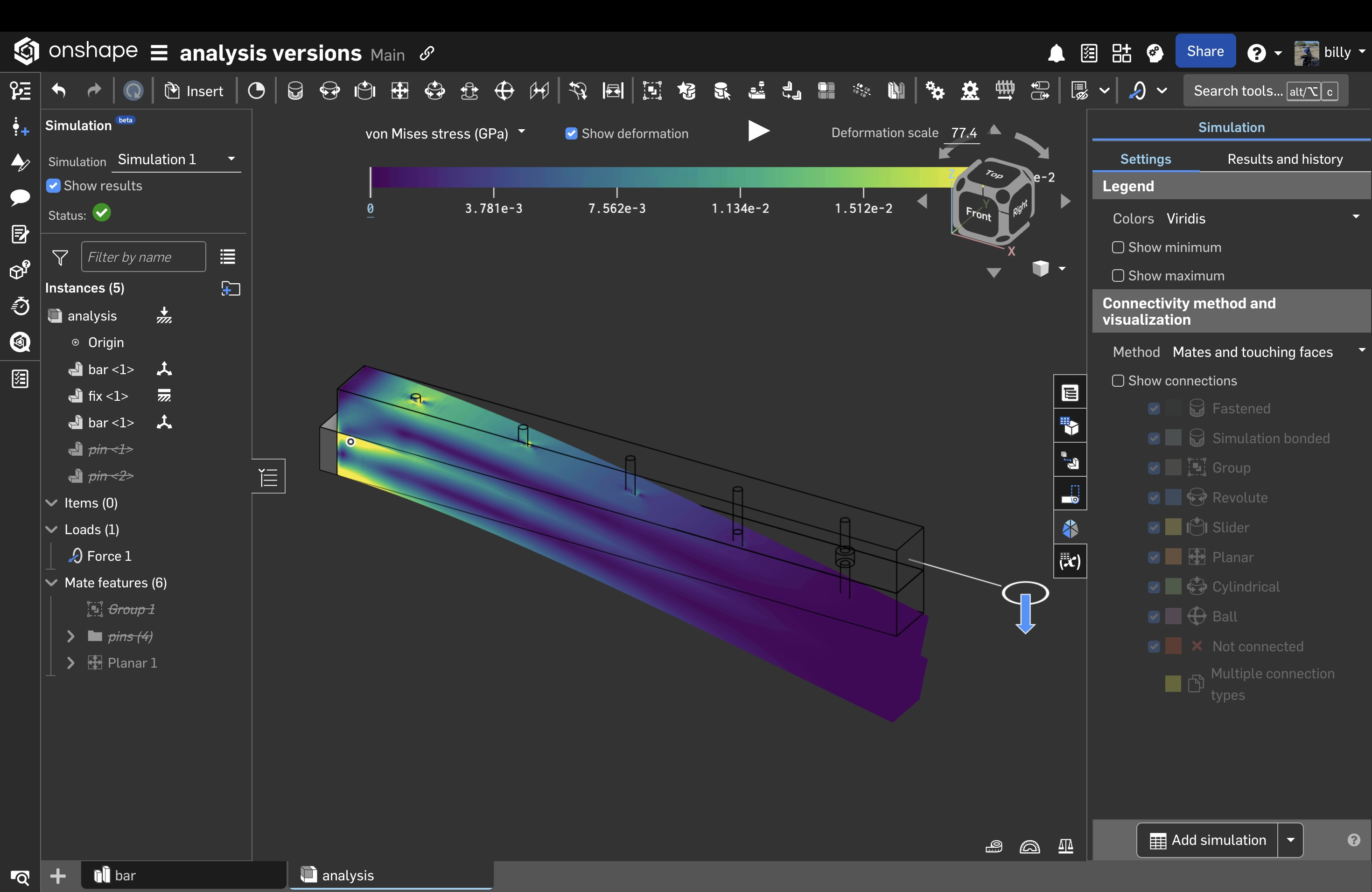
There are a million things wrong with this and mostly due to a the fact that this is linear analysis. There probably should be a discuss about these inherit issues when doing linear analysis.
0 -
Now that I have the bars behaving, I'm going to pin them together.
I'm using a cylindrical constraint in the top bar and fixed in the bottom bar.
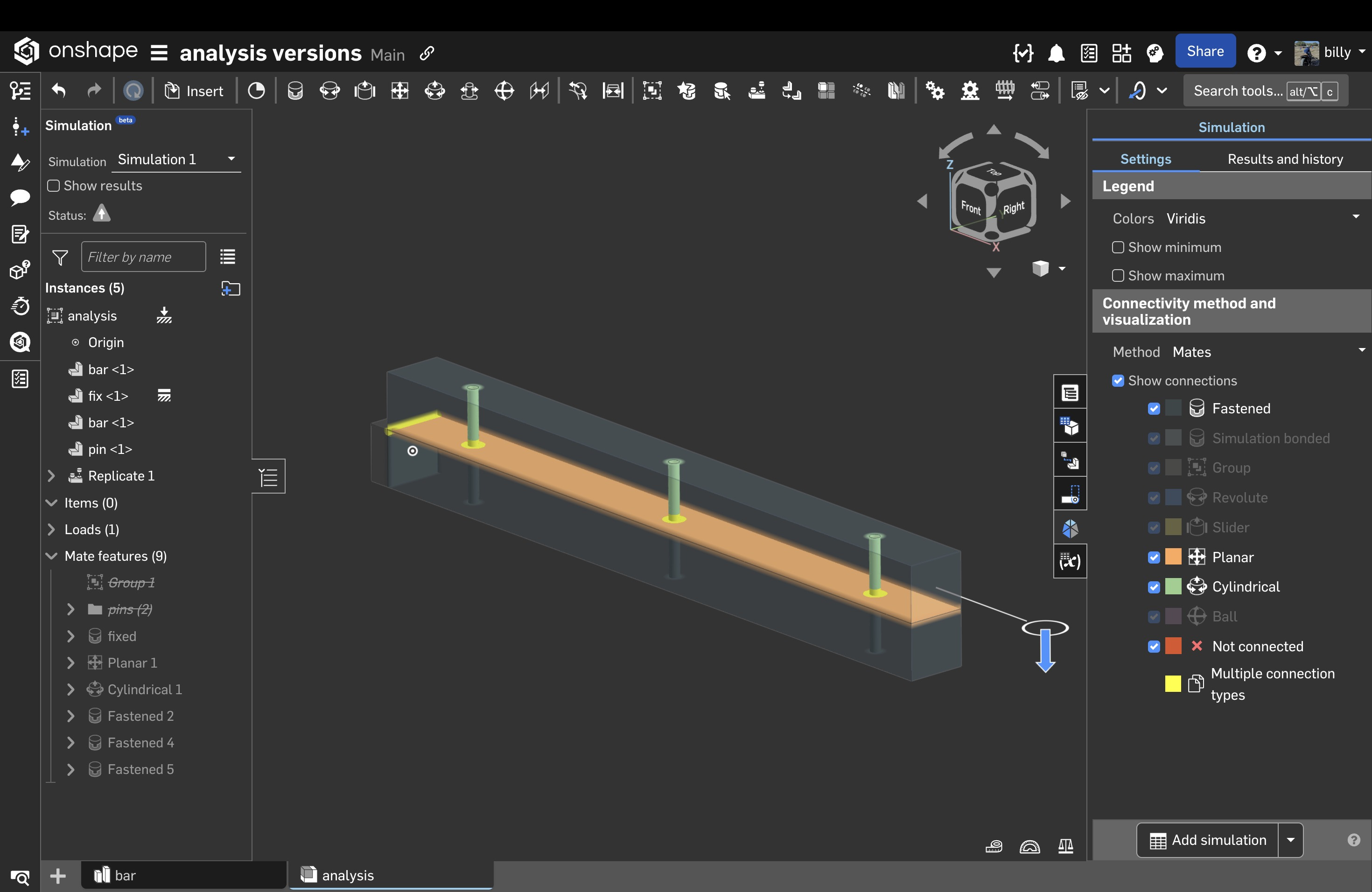
I started out using cylindrical constraints everywhere, but the pins didn't stay with the bars, they kept falling out. It looks better if the pins stayed with the bars.
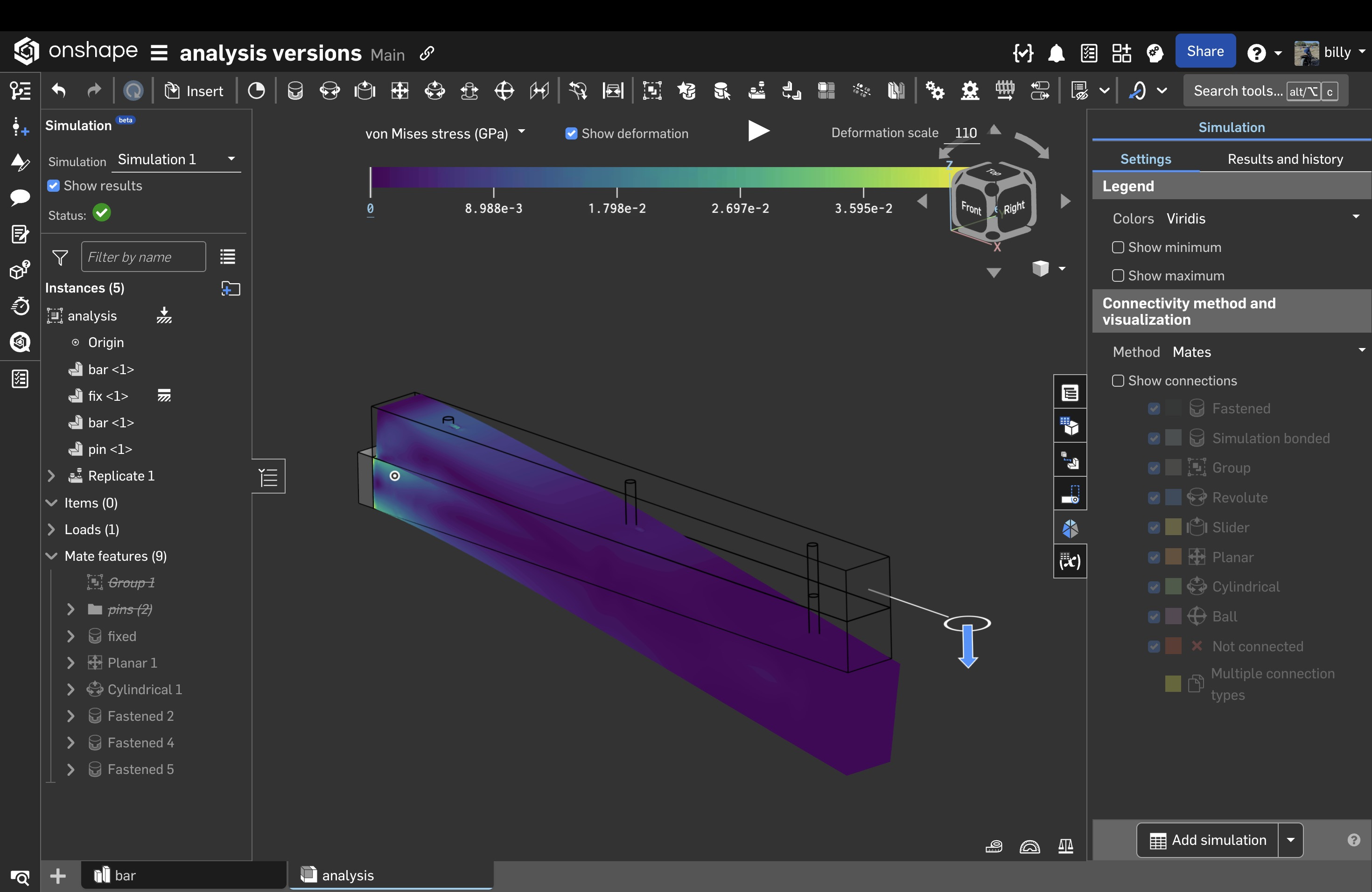
Notice how the bar ends are staying together now that they're pinned.
It's hard to see what's happening inside an analysis and I think sectioning could work better for analysis. Below is just the pins.
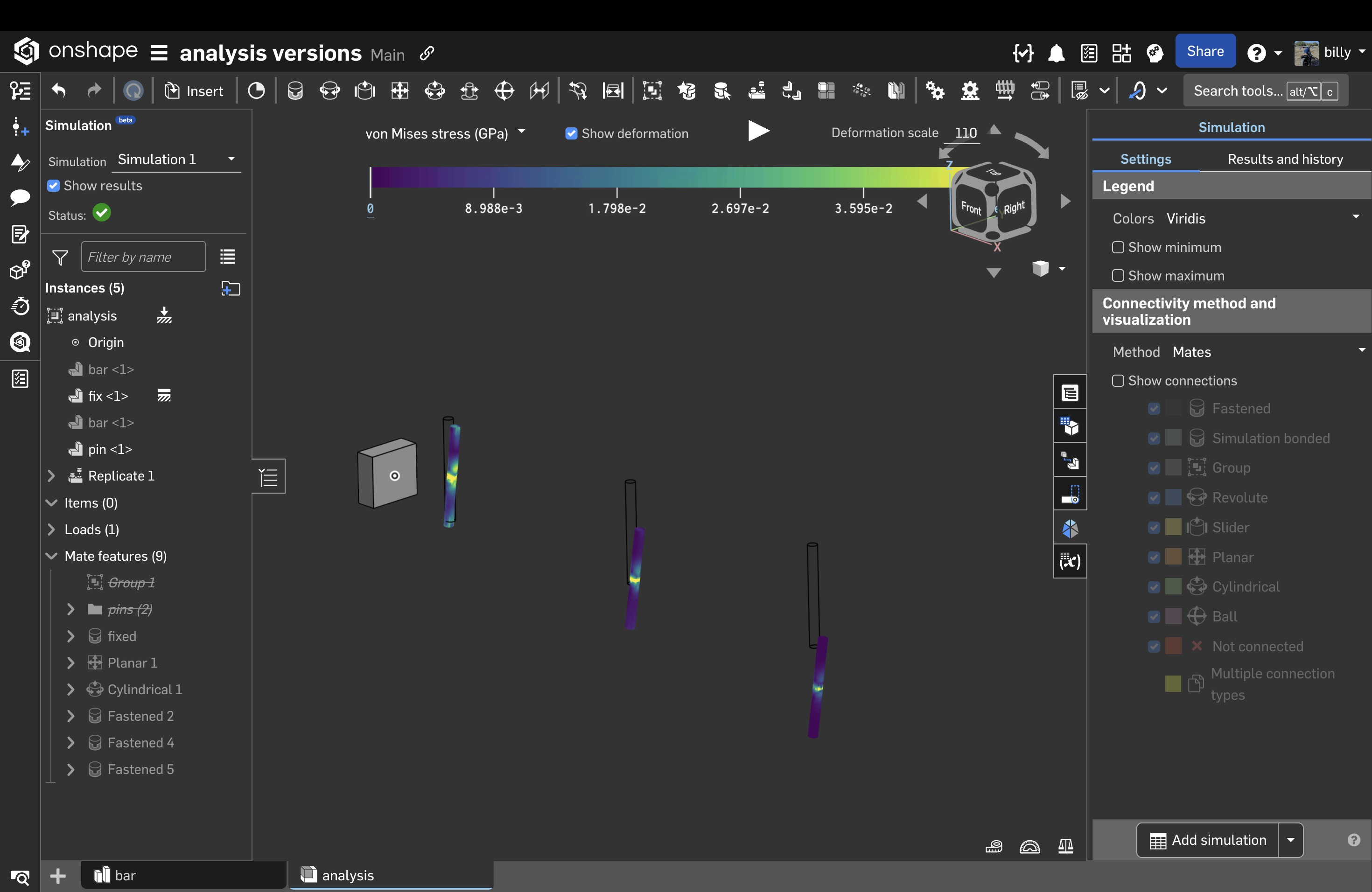
Notice how the left pin has more stress and the other have decreasing stress.
I also turned off touching and switched to mates only because constraining the pins properly with touch on wasn't working. I also tried using simulation connectors and those didn't work properly either, I guess I'm still trying to figure those out too.
The replicate instant worked ok, but you can only move 1 mate at a time, I needed 2 mates to move since each pin had 2 mate connectors attached. If you're going to analyse bolted connections, replicate instance needs to work better. Some small changes would make it perfect.
0 -
@roman_olesnicky sorry to hijack your post. This is how you do a bolted connection.
Below are bolts, it's a bolted connection right? It needs to have bolts. I preloaded the bolts or I torqued them down. In analysis packages, this is called a prescribed displacement, but you can easily mimic this with opposing forces.
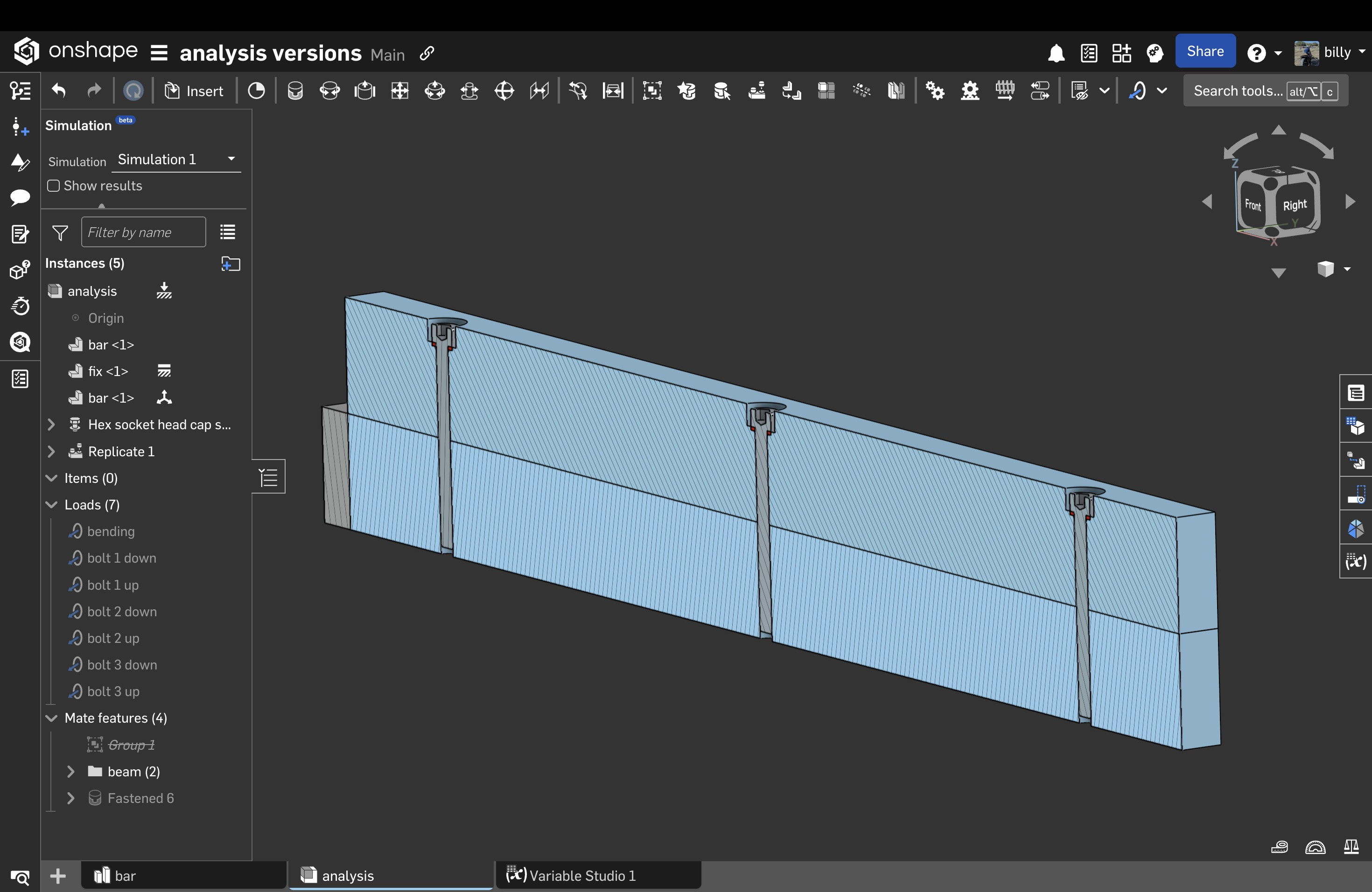
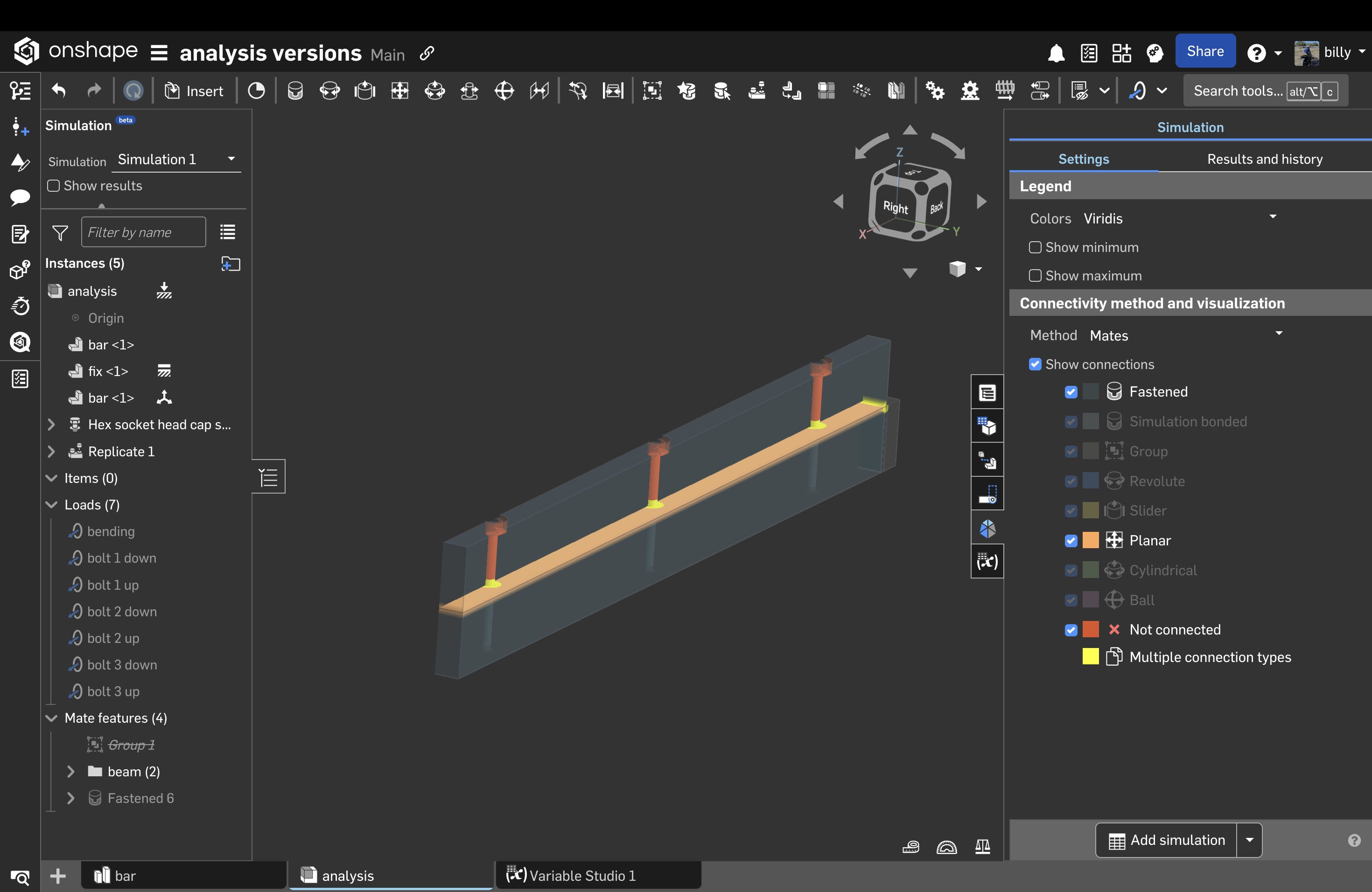
Below is almost mandatory when using many constraints and turn off touching. Thanks Eric. Replicating the bolts worked well but the forces don't replicate. This doesn't scale up and it should. The more bolts, it's more work.
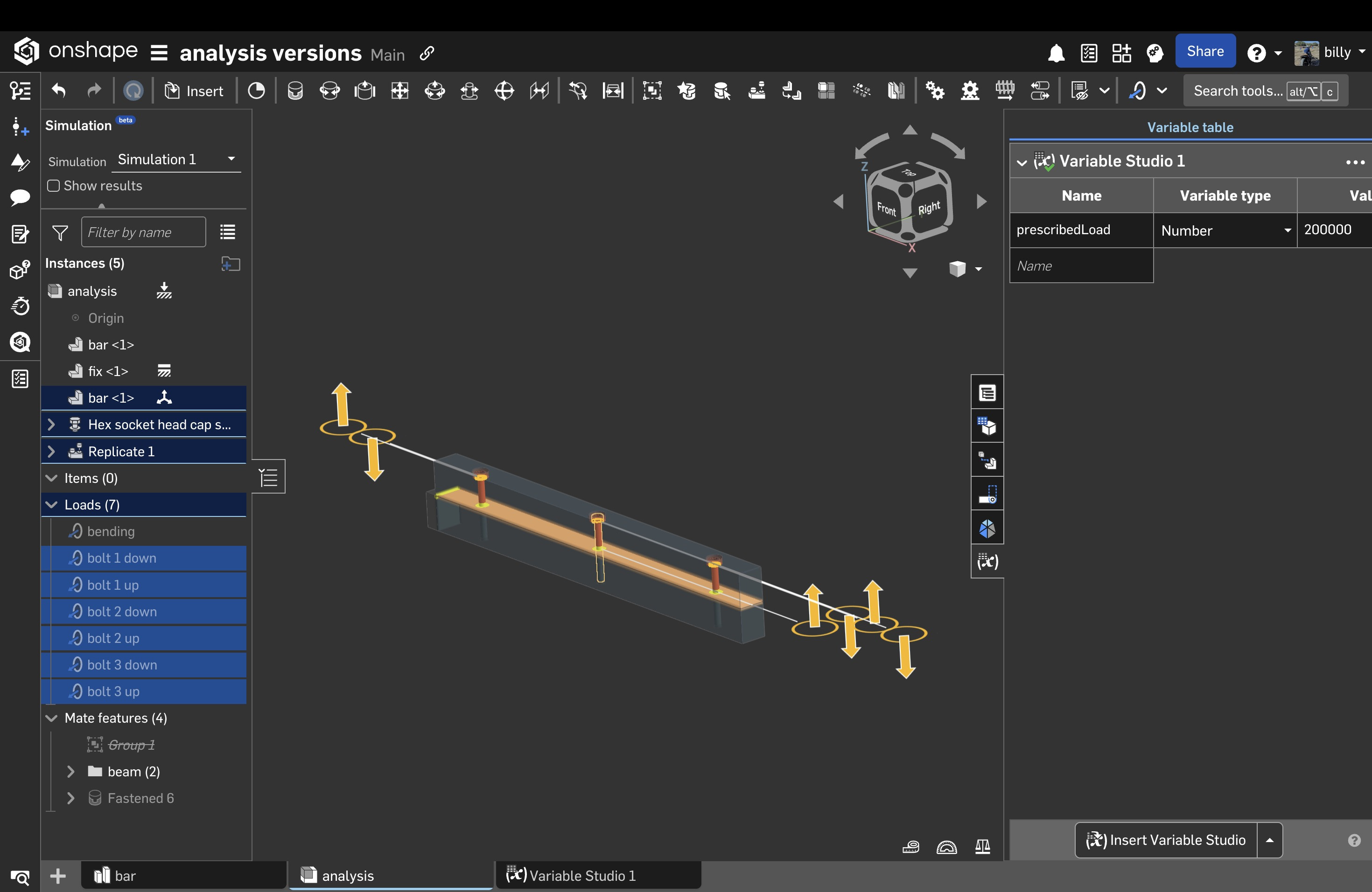
Below is the replication of forces which are mainly opposing forces. Push the bolt up and push the bar down. One thing that's really nice is that analysis accept variables. The load of all these forces were controlled by a variable I called prescribedLoad. Since opposing force aren't known, I just eyeballed by looking at the result at a 1:1 scale. It's fast and fun. I enjoyed doing that. I iterated on force to come up with the prescribed displacement.
To illustrate the preloading, I turned off the bending load so you could see the beam in compression. What's impressive is I only used 1 planar and 1 fastened constraint. It's true that replicate created 2 more fastened constraints.
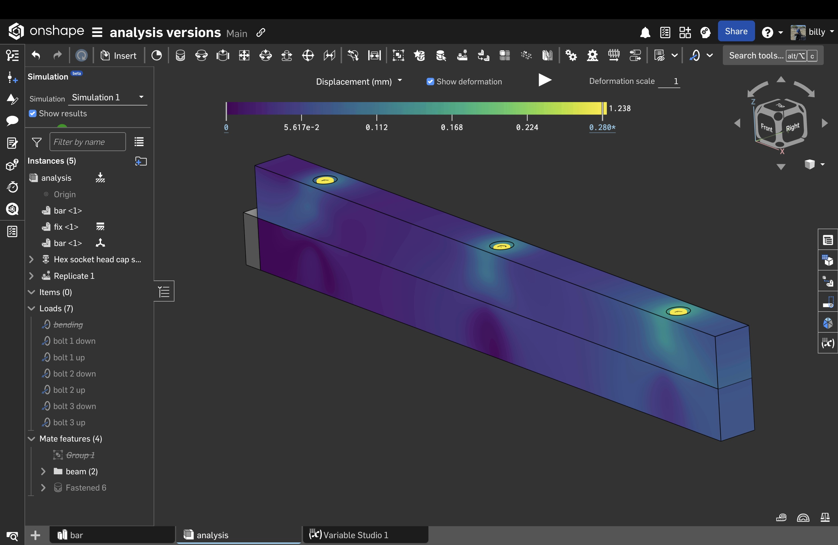
And then I turned on the end bending constraint.
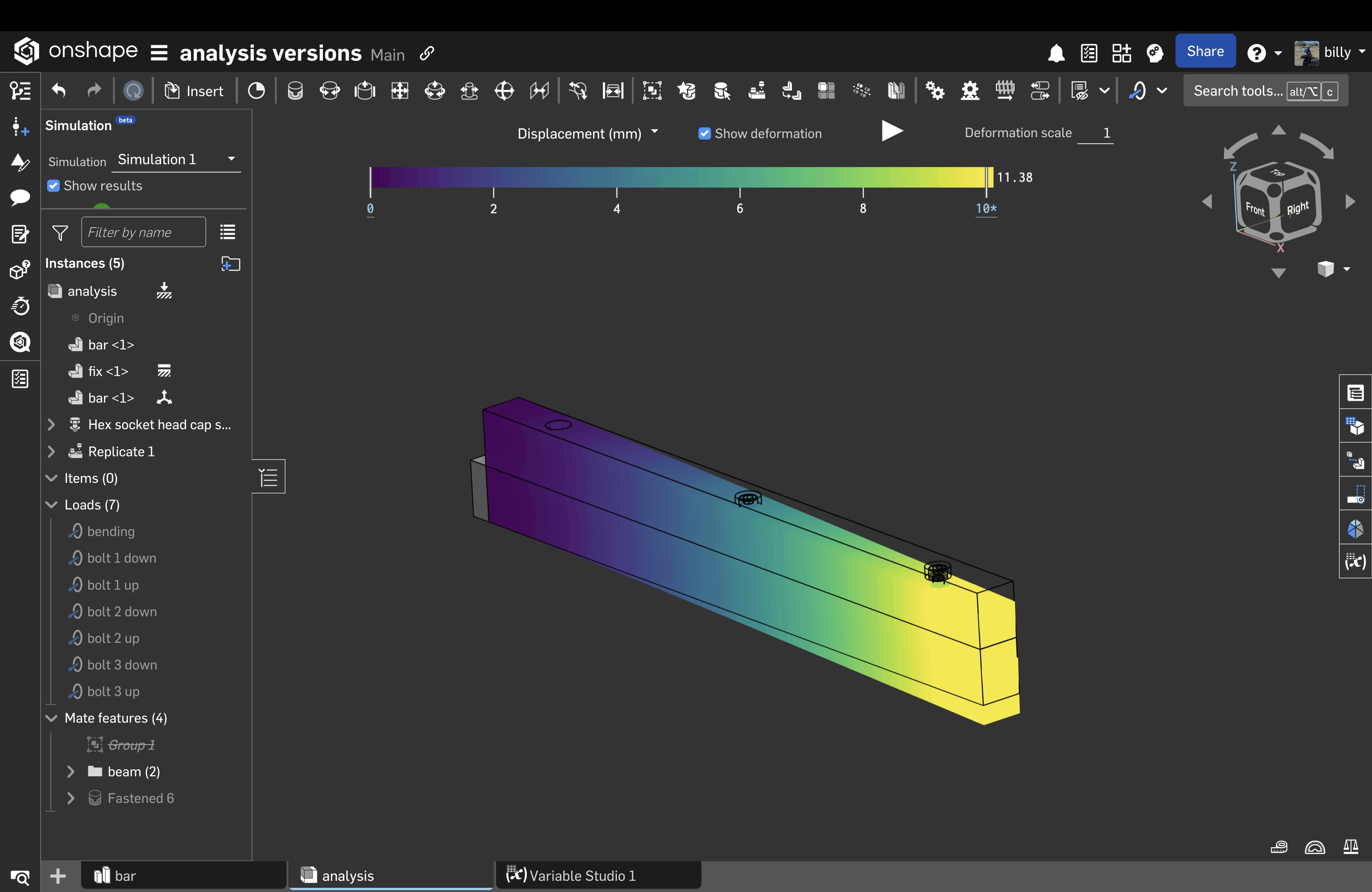
You're doing a great job, and keep it up. I rip all analysis programs apart and validate that everything it's doing. I just don't pick stuff and hope. This is what you need to learn.
One day you'll have a design review and there will be some asshole like me that's going to tear your analysis apart and they should. I look forward to those days when others pick my stuff apart. Bring it on baby, let's have some fun!
0