Welcome to the Onshape forum! Ask questions and join in the discussions about everything Onshape.
First time visiting? Here are some places to start:- Looking for a certain topic? Check out the categories filter or use Search (upper right).
- Need support? Ask a question to our Community Support category.
- Please submit support tickets for bugs but you can request improvements in the Product Feedback category.
- Be respectful, on topic and if you see a problem, Flag it.
If you would like to contact our Community Manager personally, feel free to send a private message or an email.
Create a screen inside filter

Hey folks,
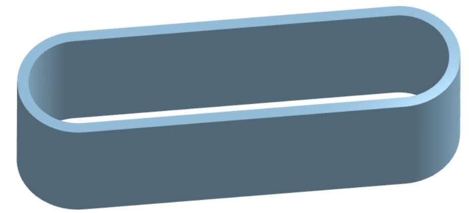
I'm trying to create a screen that would live against this filter material seen here on the inside.
Screen can be anthing such as surface with lots of holes in any patern or shape. The only need is that the screen is seen as the support for the filter material (seen here) as the air will be pulled through the filter from the inside of the oval. Think Car or motorcycle filter.
Without support, the filter material would simply get sucked into the engine! Make sense?
To be sure, I've tried several ways and have always failed. I'm just not savvy
enough with OnShape to figure it out.
Thanks in advance.
Best Answer
-
Hey Price. Ah, now I see what you are after. This Document is my hack for achieving something that may be of use. There's gotta be a more technical way to do it other than adjusting variables to get something of use.
I first made a cylinder and made a sketch of holes to Wrap on the cylinder's face and, with the Remove option, created the holes in the cylinder. The cylinder was split using a previously created plane and then the cylinder half was Mirrored using the same plane.
Another sketch of holes was created on a plane tangent to a half cylinder face. The rectangle containing the holes was made Using the edges of the opposing cylinder halves. It was then extruded the Extrude Feature was Mirrored to get the other side.
That's the gist of it. although something of a hack, it may have a method or two you might be able to employ. - Scotty
1
Answers
-
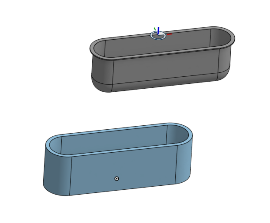
Hello. So, you just need a filter with a lip to keep it from getting sucked in? - Scotty
 0
0 -
Hey Scotty, huge thanks for the effort but that isn't quite it.
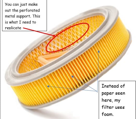
The blue part (of my drawing) is the foam filtering element. What I need can be seen in the "paper element" filter here shown and marked below. Once the engine is running, it draws air from the middle of my foam oval (and even this example paper element).
Without a mesh metal support, the foam would get sucked into the engine instantly. BTW, there are caps top and bottom to "seal the foam" which I've not included for clarity and potential ease of modeling.
Really appreciate your effort for me. Any more ideas are welcome!
0 -
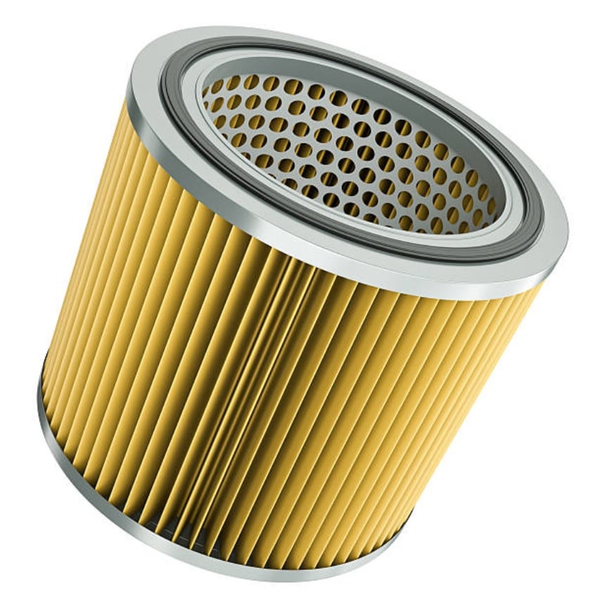
Scotty, this may be a better example of the "backing" inside a filter. Note that the perforations can be anything. Round holes, diamond shapes, squares etc. Again, TY for your thoughts and help.
 0
0 -
0
-
Hey Price. Ah, now I see what you are after. This Document is my hack for achieving something that may be of use. There's gotta be a more technical way to do it other than adjusting variables to get something of use.
I first made a cylinder and made a sketch of holes to Wrap on the cylinder's face and, with the Remove option, created the holes in the cylinder. The cylinder was split using a previously created plane and then the cylinder half was Mirrored using the same plane.
Another sketch of holes was created on a plane tangent to a half cylinder face. The rectangle containing the holes was made Using the edges of the opposing cylinder halves. It was then extruded the Extrude Feature was Mirrored to get the other side.
That's the gist of it. although something of a hack, it may have a method or two you might be able to employ. - Scotty
1 -
Scotty, are you kidding? This is EPIC and can't thank you enough.
I am just stuck on stupid and will now go see how you did this and keep that in my mind going forward.
Super creative, which I am occasionally, but was absolutely stuck this go - round. OnShape is so powerful I often don't even know what question to ask myself so I end up like the keys of an old manual typewriter (you may be too young) that can all get jammed together when typing too fast. My brain is that jumble of keys….stuck!
If you don't mind, please don't delete your solution until I have a chance to capture and study it OK?
Price
0 -
Scotty,
No worries as I've now saved a copy of your work. Again, no words beyond TY!
Stay well, Price
0