Welcome to the Onshape forum! Ask questions and join in the discussions about everything Onshape.
First time visiting? Here are some places to start:- Looking for a certain topic? Check out the categories filter or use Search (upper right).
- Need support? Ask a question to our Community Support category.
- Please submit support tickets for bugs but you can request improvements in the Product Feedback category.
- Be respectful, on topic and if you see a problem, Flag it.
If you would like to contact our Community Manager personally, feel free to send a private message or an email.
Best Of
Re: Configuration column/options disappear after switching to released Rev of part
Coming a bit late to the party here, but I have just crashed into the same problem as @S1mon, where we have set up configured sub-assemblies and performed a release of all configurations, using the handy "Configured Assembly Properties" tab. However, when trying to configure the assembly level above with these new released sub-assemlbies, the configurations columns disappears.
@romeograham you mention this:
A Released part can only be 1 configuration - think about it as a "made" part: once you have a piece of metal on your workbench - it has a certain number of holes in it. You can NOT decide that you want to see more holes or fewer holes in that piece of metal on your bench - without physically drilling more holes or filling them in.
Wouldn't it in this case be OK if all the different configurations in the assembly have different part numbers, using Configured Assembly Properties?
The one assembly tab can then show several built assemblies with unique properties, saving us for managing several more or less similar assembly tabs.
Or am I missing some logic here?
Does anybody know if Onshape is working on this?
 e_g_e
e_g_e
Re: Released Configured Part Not Configurable
I have a configured product. I've released X number of configurations for my individual parts. Now, I want to make sure I'm referencing the latest released geometry in my assembly for each configuration but I can't...
Re: Released Configured Part Not Configurable
 dt_user
Re: Released Configured Part Not Configurable
Recently, I wanted to check some clearances between two parts and verify that there was acceptable clearance in each configuration. When doing this, I also want the re-assurance of the triangle symbols in my parts list to make sure I'm checking clearances on released components.
For context, the top-level assembly includes a configured sub-assembly (also released) and configured parts (each configuration of each part is also released). The configurable sub-assembly also has configured and released parts. Each released configured assembly and part has a unique PN.
Simplified Example:
1.0 Top-Level Assembly (6 released configurations with unique PNs)
|-- 1.1 Sub-Assembly 1 (3 released configurations)
|---- 1.1.1 Part 1 (3 released configs)
|---- 1.1.2 Part 2 (3 released configs)
|---- 1.1.3 Part 3 (released, but not configured)
|-- 1.2 Part 4 (6 released configs)
|-- 1.3 Part 5 (6 released configs)
|-- 1.4 Part 6 (released, but not configured)
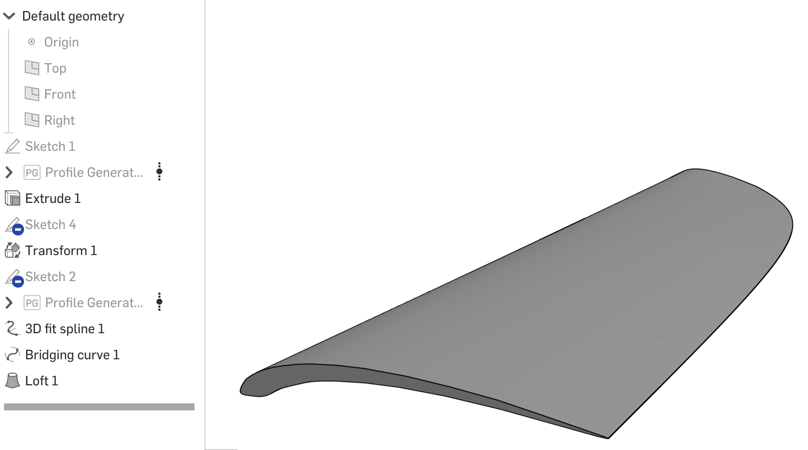
Re: How to iron out wrinkles and fill in concavities in lofts?
Edit curve with degree 5 and multiple spans is pretty good at making things smooth.
I would look at adding guide curves that are created using Bridging curve. Paths aren't often great with loft in my experience. I would also look at Loft or Boundary surface and build that transition in multiple steps instead of trying to get it to do everything at once. You're also building off of swept edges and lofted edges which are overly complex.
I would back up a little and try to clean up and simplify every surface or curve. Profile Generator is nowhere near as clean as HAVF. Similarly, Freeform curve was a nice tool, but bridging curve or careful use of edit curve to clean things up would help. Boundary surface will often give you more control over surface complexity than loft.
 S1mon
S1mon
Re: New FeatureScript: Plastic Threads
Hey @kenn_sebesta167,
Thanks for the comment and recommendations. I'm sorry I didn’t get back to you sooner. I haven’t looked at the forums in a little while.
I changed the layer thickness error to show up as a tooltip and to show the “correct” layer thickness. Of course, by “correct” layer thickness I mean the layer thickness ensuring that a single layer captures the flat section of the thread profile. This is an estimation of what would work and in my experience, it prevents tiny threads from printing with too little detail/resolution.
The error you are getting with the cone removing geometry from your part is an oversight on my part in testing. That is the chamfer cone cutting the chamfer on the threads at the exit of the hole. The chamfer cone should scale with the pitch of the threads to not interfere with the rest of the part but in that circumstance, it was not scaling correctly. I have fixed the error so you can thread the hole without it cutting into any other section of the part.
I also updated the script to allow for many hole and stud selections. The main reason for holding off before was to prevent users from creating 10+ threaded holes/studs and then lagging the part studio until it is unusable. I realize now that kind of “hand-holding” really isn’t necessary and everyone is smart enough to figure out that this is a pretty heavy feature script to run if you have multiple starts or really fine pitch threads. The script is actually quite optimized but the predominant bottleneck for performance is the sweep and union functions which each can take hundreds of milliseconds to solve (When you add up ten 200 ms sweeps you're waiting for 2 seconds just for the part studio to load).
One last thing, in the picture you uploaded you selected a threaded M3 hole and I wanted to let you know that this script was not designed to interface with any standardized threads. If you want to, the hole/stud size needs to be the same diameter as the external thread of the corresponding bolt. So for an M3 screw to thread in, the hole would need to be 3 mm and the pitch 0.5 mm. External threads act like a die and cut into the cylinder while internal threads add material to match the external threads given the same diameter. This means that internal and external threads from the same diameter cylinders match and thread together.
With these changes, I updated the UI so it is easier to see how the more advanced features expand the functionality. I hope you can finally use this feature script how you initially desired. Let me know if you have any more issues so I can resolve them.
You can find the new version here (Plastic Thread) or you can just update the feature in your tool bar in any part studio.
Re: Compatible software file
Looks like that is a hobby-level CNC router that runs some form of GRBL for the router control. You can probably find some public files in Onshape that might be appropriate for that router. What sort of CAM system will you be using to generate toolpaths for the router and does it have a post-processor for the router? If none of that makes sense, ask more questions and someone here moght be able to help.
Re: How could I join these two points to then use it as a guide for loft?
I used 2 guides, a bridging curve and a 3D fit spline.

Re: Improvements to Onshape - August 7th, 2025
@Jason_S "We have the "always show" option in the works. There was value in getting this out rather than holding for that."
Very much appreciated - Thanks! 😊