Welcome to the Onshape forum! Ask questions and join in the discussions about everything Onshape.
First time visiting? Here are some places to start:- Looking for a certain topic? Check out the categories filter or use Search (upper right).
- Need support? Ask a question to our Community Support category.
- Please submit support tickets for bugs but you can request improvements in the Product Feedback category.
- Be respectful, on topic and if you see a problem, Flag it.
If you would like to contact our Community Manager personally, feel free to send a private message or an email.
Best Of
Re: A new one for help😊
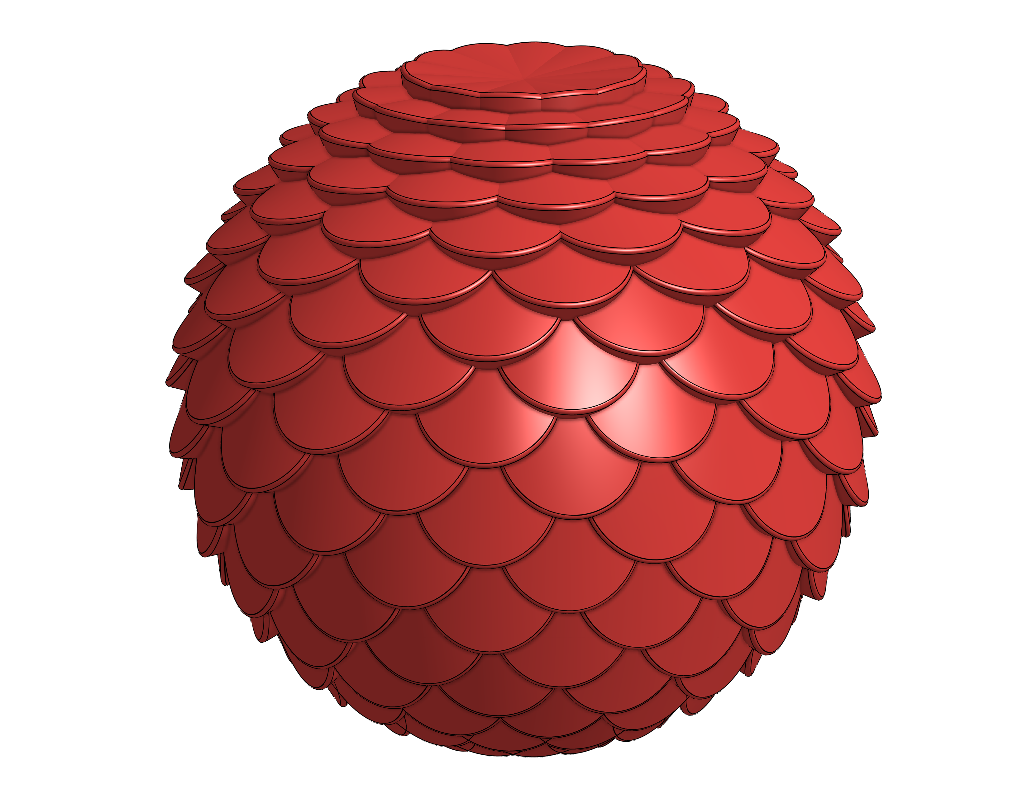
With the current version of Texture there is a bug when trying to do spheres. If you leave a small region open at the top and bottom, it will work. The new version fixes this issue but isn't complete yet.
Here is an example of how to do it with the current version of Texture:
https://cad.onshape.com/documents/172bc597d36da1751ec9c3cc/w/9a9b0d105898026566cd42fc/e/50af4d914f…

Re: Is it possible to search the public documents by Owner?
I just wanted to find a modell of the specific creator but the search is a mess,
Please add this feature.
please, or at least explain why is it not there and can leave with it. but do not leave us in limbo. please

Re: Fillet complex corner
I think i solved it by making each individual rib a separate sweep following its own path, then a boolean to combine the parts