Welcome to the Onshape forum! Ask questions and join in the discussions about everything Onshape.
First time visiting? Here are some places to start:- Looking for a certain topic? Check out the categories filter or use Search (upper right).
- Need support? Ask a question to our Community Support category.
- Please submit support tickets for bugs but you can request improvements in the Product Feedback category.
- Be respectful, on topic and if you see a problem, Flag it.
If you would like to contact our Community Manager personally, feel free to send a private message or an email.
Best Of
Re: flat pattern projection in drawing
I believe the option to flip the direction was added in the "sheet metal feature" since this thread was created. Although I have to admit it's not super clear that what this does:Michael_Bills said:I agree, the way this is implemented makes my drawings look unprofessional.


New Feature: Lefty Flip
After seeing loads of forum posts about the want for an assembly mirror, and lots of my team's gripes about wanting non-assembly mirrors that flip the original input parts instead of creating new ones to maintain the flow of downstream operations I decided to do something about it. This is not an assembly mirror feature. This is just a tribute.
I present to you Lefty Flip, which allows you to create left handed configurations of your parts while fully maintaining original part IDs, edge IDs, face IDs, pretty much everything I threw at it in one afternoon's worth of noodling. This means any mates you define at the assembly level for your right hand configurations of parts will also be defined for the left hand configuration when you change between them. Assuming you mated things any kind of reasonable.
To demonstrate I found a copy of a Fender Stratocaster assembly someone modeled and published on the public docs, but left out all the lefties.
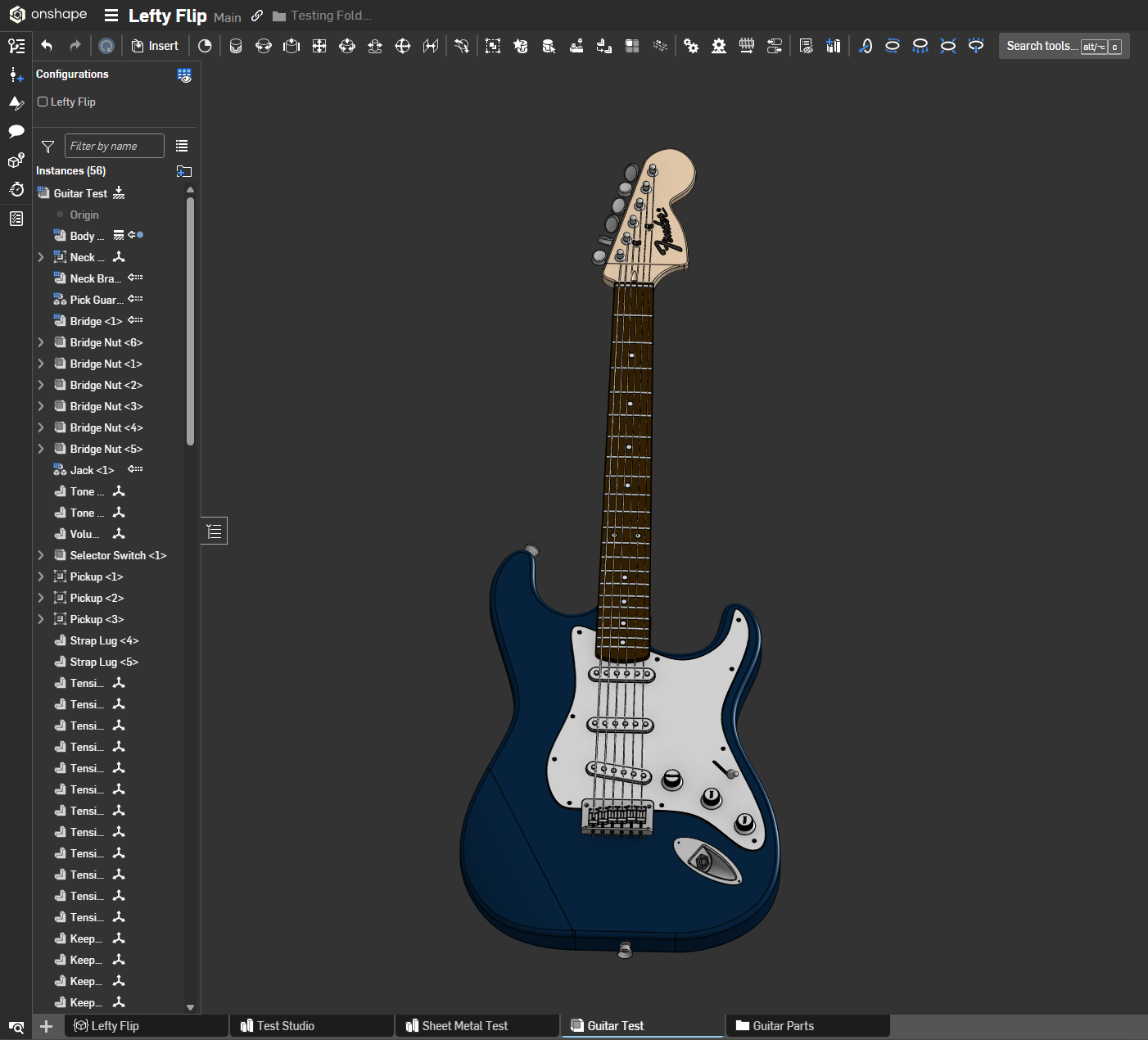
And then applied the script to 3 part studios for the parts that would be flipped on a lefty guitar and none of the ones that wouldn't

Lefty Flipped.
Normally creating a left handed configuration of a product would require forethought and intent and good assembly structure and you'll still end up with a folder of suppressed mates at the end that you'll look back on later confused at how things are meant to relate to one another. Heaven help you if it isn't your model. Now you just need one feature and a configuration checkbox.
Just select the bodies you want to mirror in the part studio and optionally define a mate connector to center your flipping operation on. If nothing is selected it will use the part studio's origin as the center. It does do a left to right flip and not a front to back or top to bottom. Our company operates under Earth gravity but let me know if you work on parts for space and want the option for front to back or top to bottom flips and I might update this to add those at some point.
And because my team wouldn't live without it, it does sheet metal too. But only if you flip everything in the context at once because things were getting unstable when I tried to do only single pieces out of context. Probably that's your intent with a left handed sheet metal model in most cases anyway.
Now if only I was any good at drawing icons…

Re: How to add curved channels into parts
Thank you for the document, very helpful! For the line you made, was it a 3 point arc that you then offset and them mirrored?

 Arkelic
Re: How to Extrude along a surface of cylinder while making a 90 degree twist
I made this video a long time ago, there may be improvements that make my method obsolete…

Re: Custom Feature: Cable/Wire Routing
Changelog for release 1.198.1
⭐ Fixed issue with CSV files containing spaces

Re: How to Extrude along a surface of cylinder while making a 90 degree twist
Yes, as you say it's hard to get this stuff right in CAD. I've modeled cams in Solidworks, which has a native swept solid feature. However, the surfaces it created were atrocious. "Hand building" is probably a better solution, but it sure would be nice if there were better tools.
 S1mon
S1mon
Re: How to Extrude along a surface of cylinder while making a 90 degree twist
This is one of those easy-to-machine but hard-to-model features that make machine shops roll their eyes at designers. The problem with the wrap feature is that it has a local context for tangency and normalcy but the 4 axis slotting operation that would be required for this part is rolling a 12mm cylinder through your part. The way to do this is to think purely in terms of the machining operation. First model the centerline of your cutting operation somehow, which wrap is useful for, but then doing a thicken operation that will match the cutter diameter, then adding in cylinder primitives at the end points of the toolpath.
Here's a photo of the interferences you'll encounter using wrap alone:

An example using some ruled surface operations and some solid primitives featurescripts courtesy of @EvanReese (though you could do this with sketch extrudes on mate connectors as well)

And a link to my doc to see how I did it.
https://cad.onshape.com/documents/82582ec2491e30f28cd4bacf/w/357f8fc6ebeac95345155eb7/e/6e6a3b0d521a696c46c1efb2
Re: Countersink Screws and Holes Mating
By the way, I work in the railway industry, and I agree on the fact that proper mating should be with conical surfaces. It's just not possible to adapt the machining in our case, as all parts comes from different suppliers. Screws are manufactures to a standard, and we design the holes to match this in all allowed tolerances of the standard.
Re: Countersink Screws and Holes Mating

Re: Can I to add measures of the Part Bounds in the BOM List?
You can use computed properties:
https://www.onshape.com/en/resource-center/tech-tips/using-computed-part-properties-in-onshape
You can adapt the example in the article to use a bounding box instead of the volume calculation.
If you don't feel comfortable with featurescript, I sell a large library of computed properties (featuring lots of common computed properties):
https://fs.place/Listings/HUK1UHJF8EQ6HS1NEVJ2SWH4BI1TOMT1
