Welcome to the Onshape forum! Ask questions and join in the discussions about everything Onshape.
First time visiting? Here are some places to start:- Looking for a certain topic? Check out the categories filter or use Search (upper right).
- Need support? Ask a question to our Community Support category.
- Please submit support tickets for bugs but you can request improvements in the Product Feedback category.
- Be respectful, on topic and if you see a problem, Flag it.
If you would like to contact our Community Manager personally, feel free to send a private message or an email.
Best Of
Re: Untrim?
Yes. Creating a new surface is nice, though it kind of breaks the chain. A feature which keeps the ID and continuity in the design process would sure be perferable, especially if we could go back when needed and untrim another side or remove or restore another internal edge.
I've been working with Spaceclaum for quite some time, an there, it was one tool that simply removed all trims when applied to a face (you got to hit it in the middle) and removed trim of one edge, extending adjacent edges when applied to that edge (you had to click on the portion of the edge you wanted to untrim).
There also was the 'Pull' tool that had an interesting functionality: You'd pull on a trimmed edge to gradually pull it back to it's untrimmed state in the first go. Pulling on the untrimmed edge another time would extend (extrapolate) it gradually as far as mathematically possible. That was very useful and very intuitive at that.
Re: Working With Outside Designers
Indeed this is an area yet to be addressed, yes it's easy to share and invite people into your Environment, but the fact that you would have to allocate one of the users accounts to someone that is already a paying user, seems very counterintuitive.
Re: Part number embossed on part?
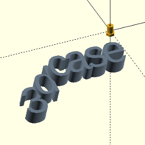
As it turns out, even FS can't save you here as all of the part properties generate after the feature list, so PNs aren't accessible to a custom feature (unless that feature is also setting the PN). I think it would need to be something with the API that reads it and updates a variable every so often. I've wanted something like this for a similar purpose. For example, if I'm iterating on 3D printed mockups and changing each one, I'd like to have the version number and date automatically added.
Part number embossed on part?
This just came up when discussing a current project on the shopfloor: Is there a way to more or less automatically emboss/imprint a part number (or some other part property from the BOM) onto a part? Maybe at a location specified by a mate connector or whatever marker may appear useful? At first glance, this appears to be a job for a FS …
The background is the shop messed up similar looking 3D printed and laser cut parts. 🤣
Re: How to create this specific mate ?
After having a closer look, you don't even need a tangent mate, you just need to put some mate connectors in well placed spots to allow for a sliding mate paired with a revolution mate. The sliding mate could have limits so that when the actuator gets near the red arm, it starts to hit the slider limit in turn pushing the red arm the correct direction.
Will need access to copy the document for further guidance.
Re: How to create this specific mate ?
My bad, I was thinking that the sharing link allows writing. I've changed the document to public, so you should be able to play with it now. Let me know if it's ok.
I've tried various configuration of sliding edges but none has worked. But I'm far from an OnShape expert, having used it until now to model simple mechanisms composed of 3D printed parts.
Re: How to create this specific mate ?
Many thanks Michael for your quick reply.
Here is a link to the document : https://cad.onshape.com/documents/e611f9c9fe382489dc6c6b31/w/aa15001cdbadba9e845ac582/e/bca21fd677662a557f8ba01b?renderMode=0&uiState=6786e3a631048d13ede0ccc0
This is a triggering mechanism I'm adding to a double pendulum I've built for a student working on an experimentation project about the chaos theory.
The goal is to reproduce as exactly as possible identical initial configurations by placing the trigger at fixed positions (thanks to an additional external support) and observe that even then, due to unavoidable infinitesimal differences, the motion of the pendulum for several trials will be completely different. The experiments are recorded with a high speed camera (240 FPS) and a video tracking app (Tracker - https://physlets.org/tracker/) is used to record the trajectory, speed and accelerations of the red and green markers at the end of the arms.
Here is the full view of the trigger :
The yellow part is some sort of piston, used to hold the pendulum arm at the chosen initial positon by placing it in the end fork. Elastic bands attached to the hooks of the piston and the blue base plate pull so that it quickly retracts and releases the pendulum at experiment start. While armed, the piston is kept in place by the red hook. When the grey horn rotates, it pulls the hook up, which makes it release the piston.
This could seem a bit convoluted as a mechanism, and one could ask why the servo horn is not used directly to keep the piston in place. It was the option used in the first version of the mechanism, but it reveals that the constraints applied to the horn by the piston are too important and in a wrong direction, resulting in high chances to have something broken very quickly. In the current configuration, these constraints are all absorbed by the rotation axis of the red part.
I hope that these explanations make my goal easier to understand.
WRT to your remark about a partial tangent which would be active only when the parts are in contact, I'd add that I'm fine with a model where they are always in contact. But even then, I've not been able to model two perpendicular edges (one on the hook and one on the servo horn edges) sliding on each other.
Thanks again for you support.
Re: from technical drawing to cad
ASME Y14.5M seems to assume that things are tangent unless specified otherwise.
 S1mon
S1mon
Re: from technical drawing to cad
I like it, an assertion made on a derived assumption…..I will have to remember this 😎
Re: That One Time Onshape Saved My Deadline—What’s Your Story?
Well, it appears the point here is it helps to prevent these pinches from even happening.
Only yesterday was I in an external meeting, pre-production samples were brought in from the shop and and we discussed some minor ussues found (supplier of the display panel used had made changes that affected the bezel position in the latest batch).
So I asked if I could use any computer in their office, opened Onshape and made the required changes to the display mount, to correct for the offset, had my colleague look at it remotely, sent a link to their shop floor and the tooling company to download the updated files and they were good to go before I was even on my way back home.
Had I used a locally installed CAD on my desktop PC, there would have been a delay of at least one day.


