Welcome to the Onshape forum! Ask questions and join in the discussions about everything Onshape.
First time visiting? Here are some places to start:- Looking for a certain topic? Check out the categories filter or use Search (upper right).
- Need support? Ask a question to our Community Support category.
- Please submit support tickets for bugs but you can request improvements in the Product Feedback category.
- Be respectful, on topic and if you see a problem, Flag it.
If you would like to contact our Community Manager personally, feel free to send a private message or an email.
Best Of
NEW tutorial: Surfacing Deep Dive
Hey folks. I finally got around to making a video I've had on my mind for a while to demo a whole ton of surfacing techniques in one go. If you do (or aspire to) surfacing in Onshape I hope you'll give it a watch. Buckle up though… it's hefty.
 EvanReese
Re: Configurations - suppressing folders
As @_anton commented, there is an improvement request open for this, make sure to vote for it!
Re: Improvements to Onshape - July 18th, 2025
From the Changelog:
- Improve Documents page to retain expand/collapse state sections
OK!!!
Re: Improvements to Onshape - July 18th, 2025
@Tony_C_ Yes are aware of an issue with search:
https://status.onshape.com/incidents/ch70j37whngv
Re: Improvements to Onshape - July 18th, 2025
Searching at the top Company level yields zero results.
If I go into 'recently opened' or a folder, it works and populates.
 Tony_C_
Re: Improvements to Onshape - July 18th, 2025
Configuration updates! 😍 Happy early birthday to me! 😎
Improvements to Onshape - July 18th, 2025
This release contains a wide variety of features and improvements touching virtually all areas of the product: Configurations, Assemblies, Surfacing, Drawings, Data Management, as well as CAM and Render Studio! We hope there's something out there for everyone!
CAD IMPROVEMENTS
CONFIGURATION INPUTS IMPROVEMENTS
There have been several usability improvements to Onshape configurations, specifically around defining and managing your configuration inputs.- The assigned default value for a configuration input is now displayed in the configurations panel
- Configured dimensions can be renamed
- List values can be reordered by drag-and-drop
- Configuration inputs can be reordered by drag-and-drop
- You can expand or collapse all configuration inputs in one click
ASSEMBLY INTERFERENCE DETECTION - TOP LEVEL ONLY
You can now filter assembly interference detection results to show top-level interferences only.MARK-UP IN REPLY COMMENT
Reply comments can now include mark-ups, attachments, and can tag entities in the same way an initial comment can.ASSEMBLY PERFORMANCE PANEL IMPROVEMENTS
The Assembly Performance panel displays an icon when it detects longer than expected mate solve times. Expanding the panel will display a message at the bottom, providing suggestions as to how to improve mate solve times.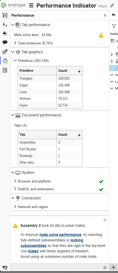
TRIM FRAME WITH MATE CONNECTOR
The Frame trim feature now supports the use of a Mate connector as a face selection with which to trim.DXF / DWG EXPORT UNITS
You can now override the default units when exporting a DXF or DWG.STRAIGHT/PARALLEL PIPE TAP THREADS
You will now find Straight pipe tap thread types in the Hole feature.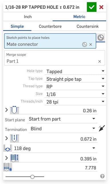
As you might expect, these new standards are correctly called out in Part studio hole tables, as well as hole callouts and thread representations in Drawings.
SHEET METAL FLAT PATTERN VIEWS - PROPERTIES
In the Drawing properties, under views, you will now find several additional controls for the line styles and colors of different sheet metal features in your flat pattern views.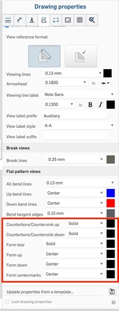
SURFACING IMPROVEMENTS
CURVE / SURFACE ANALYSIS IMPROVEMENTS
The Curve/Surface Analysis tool now displays control points, knot points, polynomial degree, and number of spans.ENCLOSE - PREVIEW GAPS
The Enclose feature now previews any gaps on screen that would prevent the feature from rebuilding.DATA MANAGEMENT IMPROVEMENTS
STRUCTURE VIEW IMPROVEMENTS
Structure view now shows an icon when a contained reference has been been obsoleted. This is also true for referenced drawings when using the Show drawings feature. Additionally, an export icon is available directly from the Structure view page, allowing you to export individual elements without having to open the containing document.COPY LINK FROM VERSION AND HISTORY
You can now directly copy the URL to any point in the Version and history graph, without having to open that node.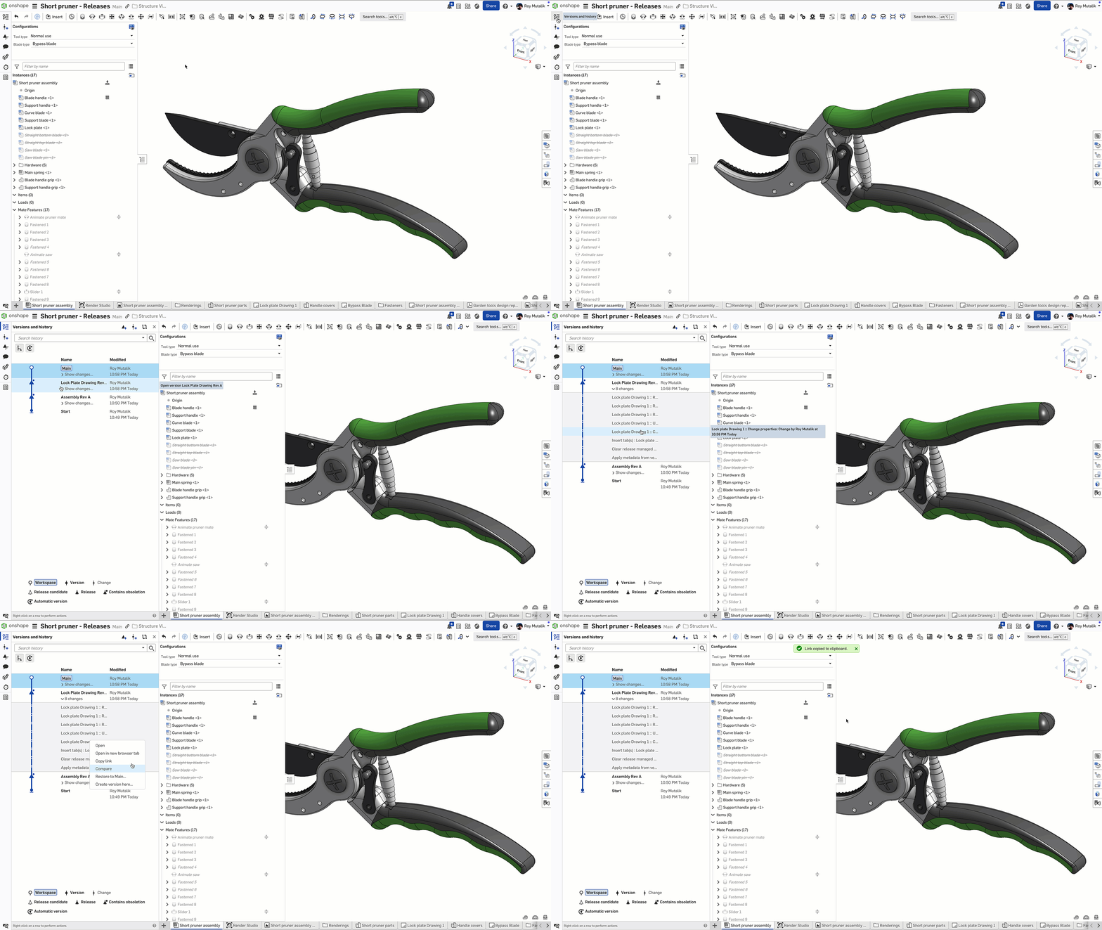
SORT FOLDERS IN GRID VIEW
While in grid view, you may now sort your folders alphabetically, reverse-alphabetically, or by last modified.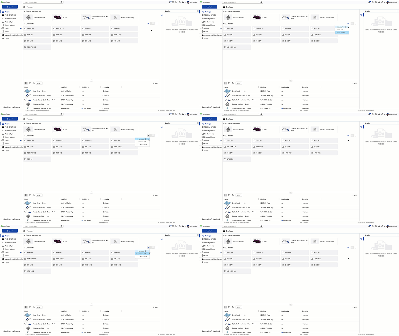
NOT REVISION MANAGED - PART STATUS
Any parts that are marked in their properties as Not revision managed now display this part status in the assembly instance list properties.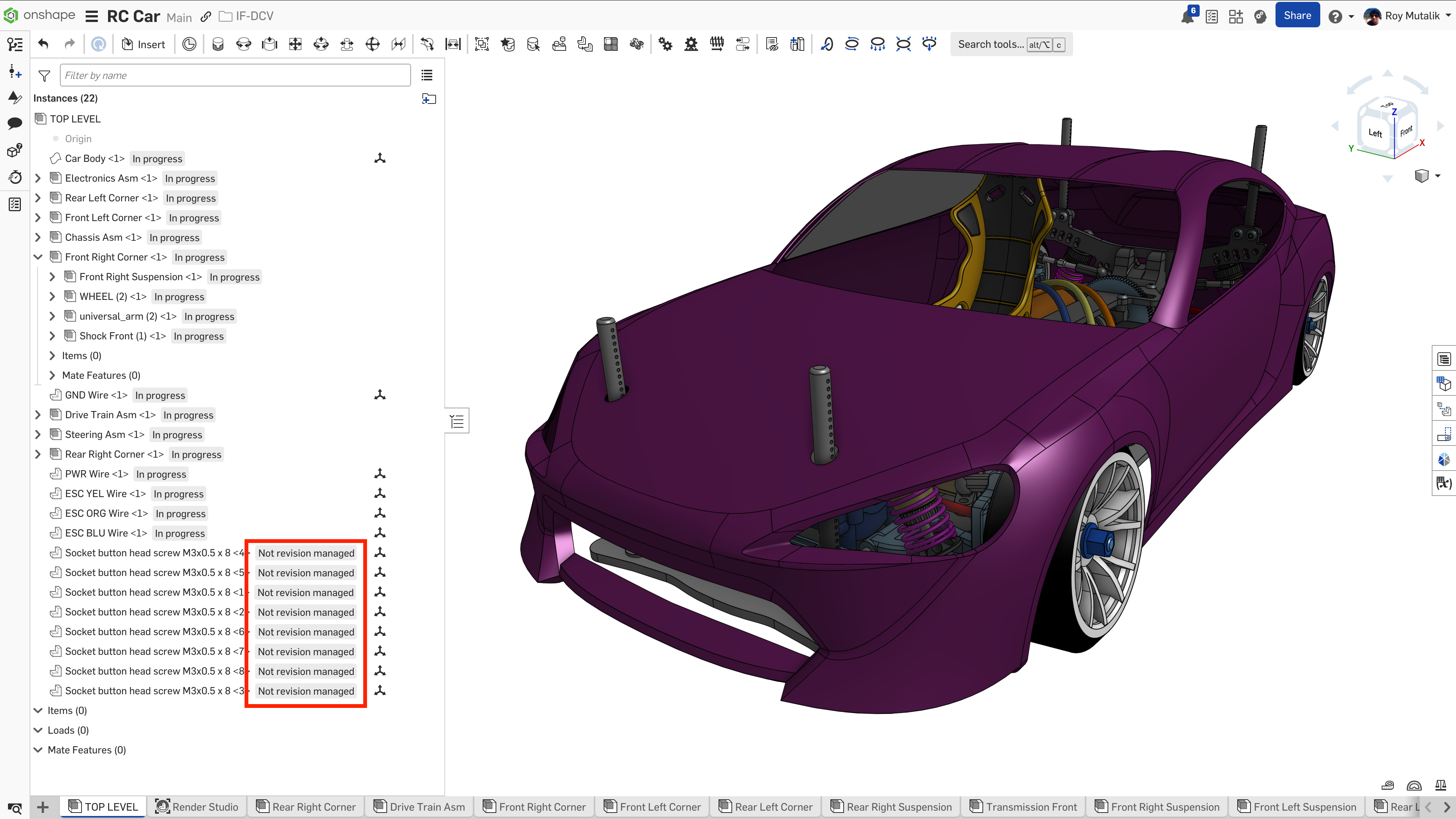
RENDER STUDIO IMPROVEMENTS
PANORAMIC AND STEREO RENDERING
You can now build and export panoramic exr/hdr files for use in a render studio scene. These panoramic renderings represent and the environmental lighting for a scene that you can then use to render your subject in.Panoramic scenes (such as the default ones provided in Render studio) are otherwise complicated to create, and often require expensive physical hardware to photograph. Being able to define them yourself in a Render studio allows for unmatched control of your lighting environment, for both total unique or very consistent results across multiple renderings.
For full documentation on this feature, please visit the help page.
DRAG-AND-DROP APPEARANCES
The default behavior when dragging and dropping appearances to the graphic area has changed. The appearance will now default to being applied to the entire part, rather than the individual face.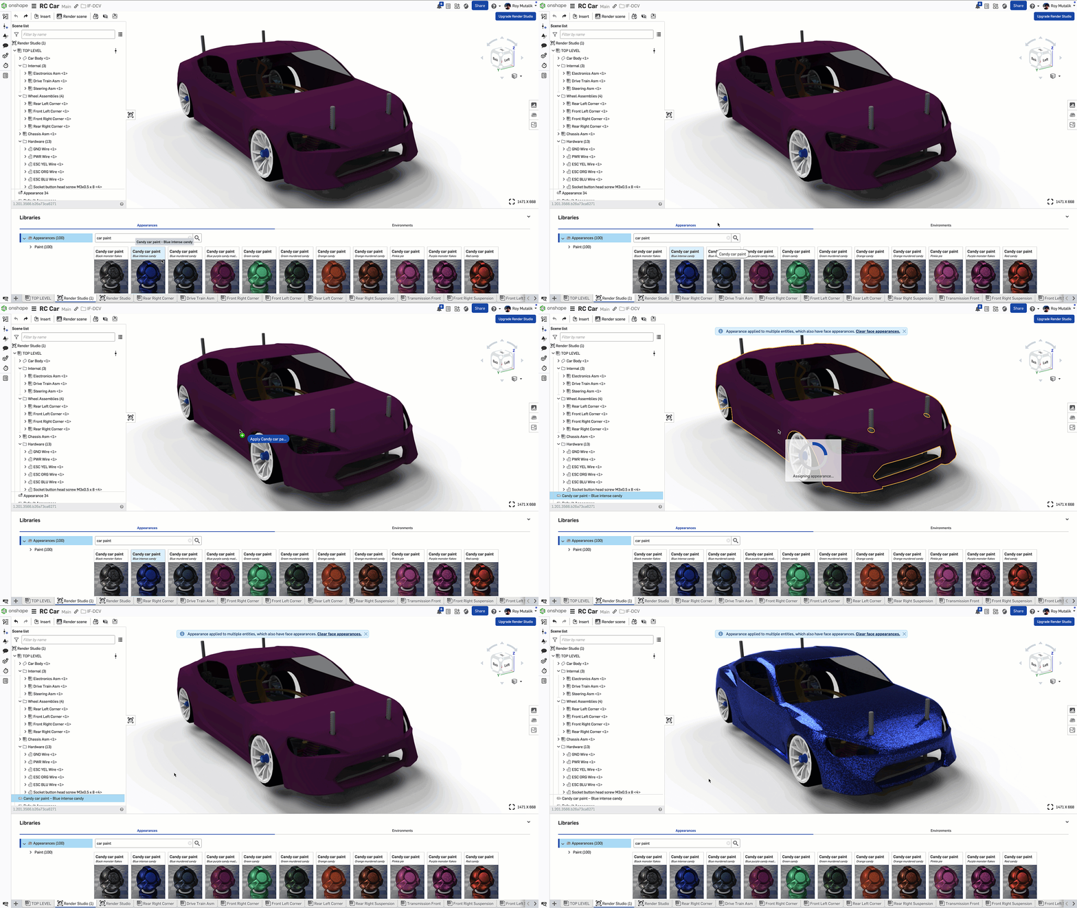
ASSEMBLY FOLDER STRUCTURE
Render studio now maintains the assembly folder structure of instances that you have defined in your Onshape assembly.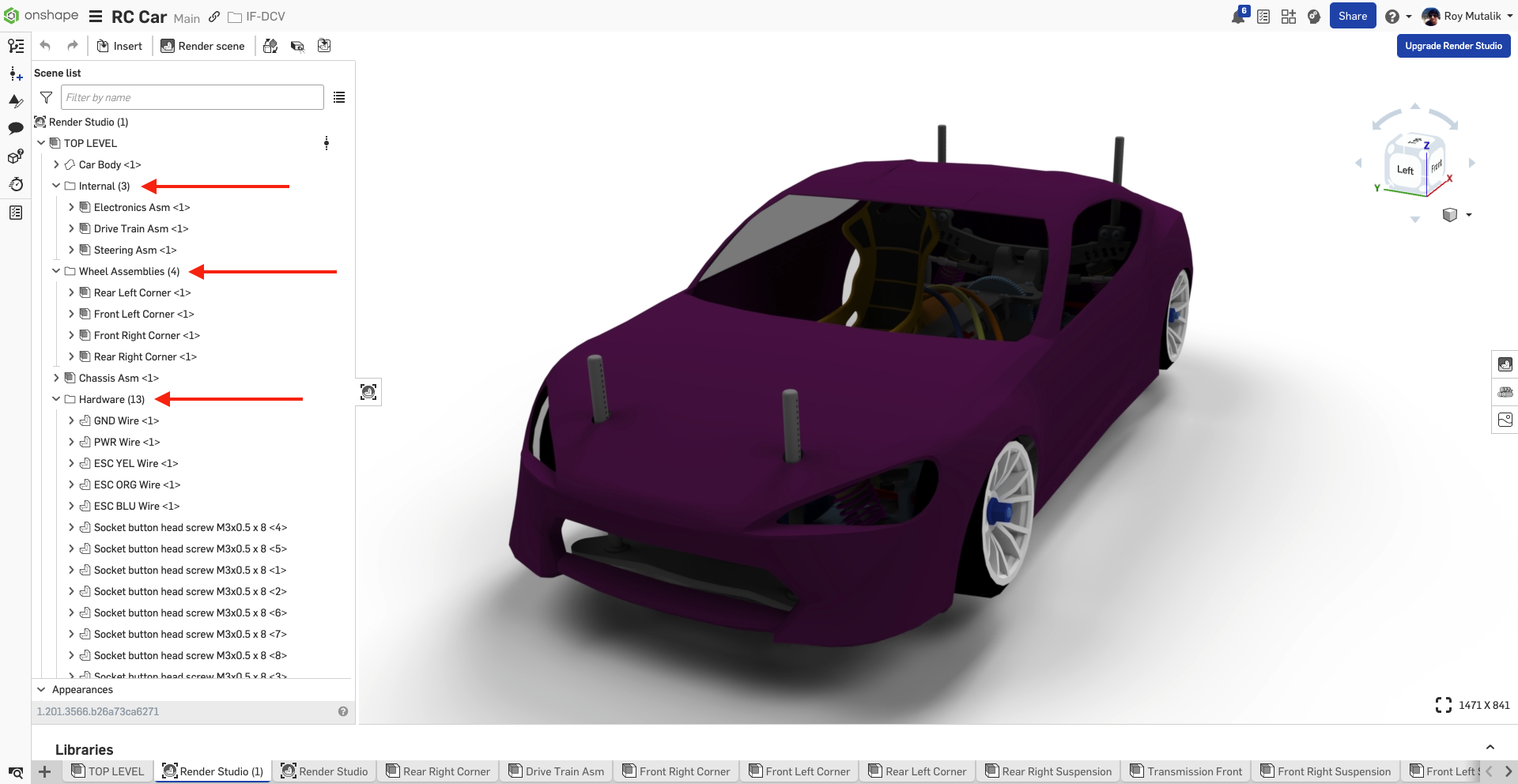
CAM STUDIO IMPROVEMENTS
TOOLBAR UI
The CAM Studio interface has been updated to a toolbar-based design. Inserting, Defining jobs, Machines, and Setups will feel much more intuitive to an Onshape-based environment by selecting features from a single toolbar across the top of the graphics area.Please take a moment to try out these new features and improvements and leave your comments below. For a detailed list of all the changes in this update, please see the changelog.
 Roy_Mutalik
Re: Configurations - suppressing folders
Was watching this and was about to add that it's easier to suppress stuff before "adding to configuration" (for things that you only want in one configs). But then I got near the end the video ;)
Re: Improvements to Onshape - June 27th, 2025
Sheet metal Loft. :) Right @sebastian_glanzner


