Welcome to the Onshape forum! Ask questions and join in the discussions about everything Onshape.
First time visiting? Here are some places to start:- Looking for a certain topic? Check out the categories filter or use Search (upper right).
- Need support? Ask a question to our Community Support category.
- Please submit support tickets for bugs but you can request improvements in the Product Feedback category.
- Be respectful, on topic and if you see a problem, Flag it.
If you would like to contact our Community Manager personally, feel free to send a private message or an email.
Best Of
Re: How to achieve parametric- or feedback friendly design using frames
I have a variable for the frame size, and the frame is square tubing, so I could have done some stuff with 1/2 the frame size, but I didn't really consider that until I had gone down this path. If/when I do a lot more frames, I'll certainly plan things out a little differently.
I'd also like to see some more flexibility with the frames feature, like the IR that I shared. I could also see things where a reference could be two points so I don't need to add 3D Fit Splines or Sketches or Routing Curves to add elements between some existing points/verticies.
I'm sure that people that use Frames all the time have more wishes.
 S1mon
S1mon
Re: How to achieve parametric- or feedback friendly design using frames
@S1mon I've got a number of projects I'm juggling right now where all the frame bodies are defined by edges or faces of solids and I'm currently getting around the cornering problem by moving faces in by half a frame width but that's not gonna be stable if I decide to change the frame standards at any point. All of these things are reasons I'm weighing a refactoring of the frames tool but to do it the way I'd really like I would need the ability to make a separate tab for the surface body definitions required to implement "simultaneous frames" like was done for sheet metal. That would definitely require some prerequisites to be met by the internal dev team at Onshape though.

Re: How to achieve parametric- or feedback friendly design using frames
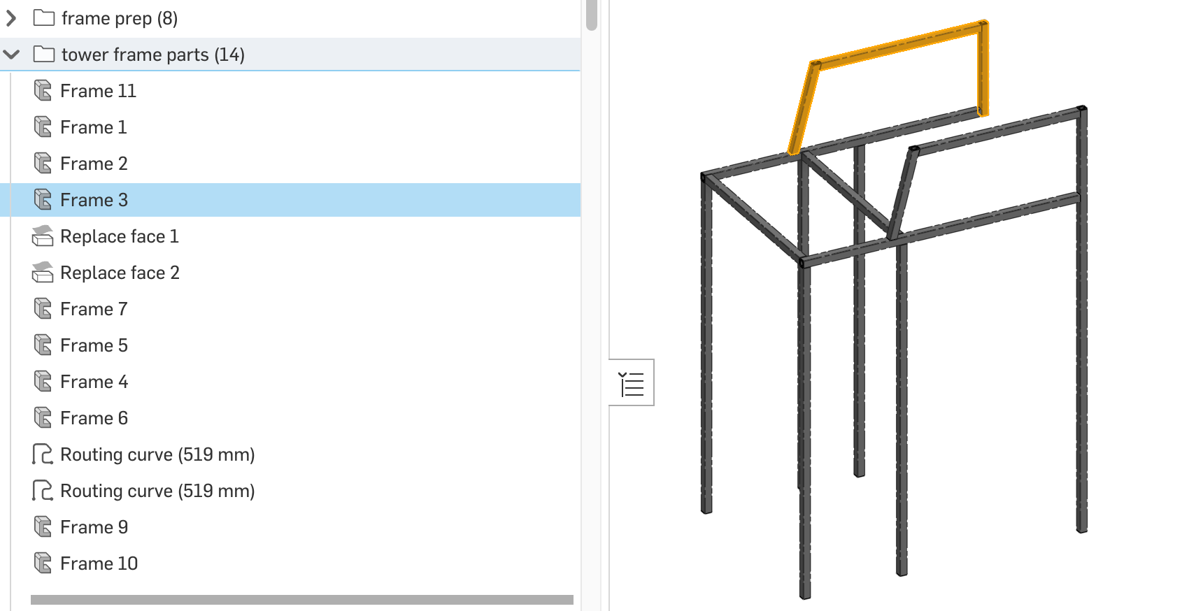
I've made a custom frame profile for one project and figured out how to add the tags. That's not the problem I was discussing.
The issue I'm having is that this frame took multiple Frame features because I couldn't choose different points for different frame elements. Also the topology drove me to need more Frame features than I would have liked. In a few areas I could get several frame parts in one feature (see highlighted feature), but overall it was awkward. I suppose if I had started the reference sketches to all be on the center of the tubes it would have cut down on the complexity. But I wanted to reference corners which don't always work out neatly to be the same for all the elements.
 S1mon
S1mon
Re: Improvements to Onshape - August 7th, 2025
Great improvements - Thank you!
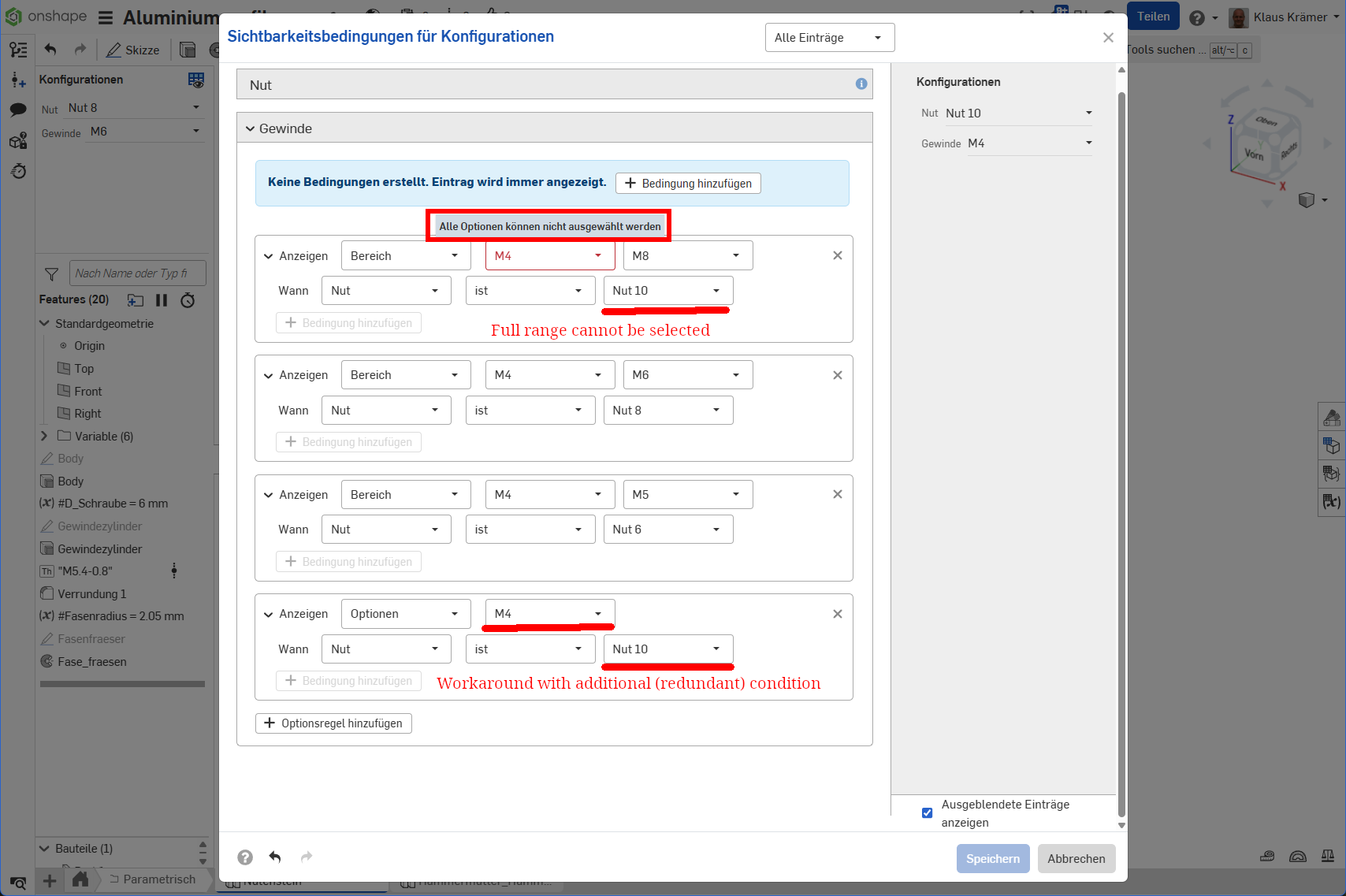
But Configuration Visibility Conditions are lacking the possibility to choose the whole range of options.
Imagine you have 3 sizes of T-Nuts for aluminum profiles in dimensions for slots 6, 8 and 10 mm. Options then provide inner threadings of 4, 5, 6 and 8 mm.
Selecting "Nut 10" (Slot 10 mm) should show all threading options from 4 to 8 mm. But you cannot use the whole range of options as there appears an error message "Alle Optionen können nicht gewählt werden" (You cannot select all options). You can see that in the uppermost box. But a workaround is to leave one option open (e.g. like I did "M4") and subsequentially add an additional condition for M4.
I think it's more of a bug than an inconvenience as redundant conditions are always prone to cause problems.

Re: How to mirror hole?
I think it would be great if those options in those types of tools were not hidden in a drop down. It would aid in the tool discovery process for new users as well.
 MDesign
How to mirror hole?
Newbie here!
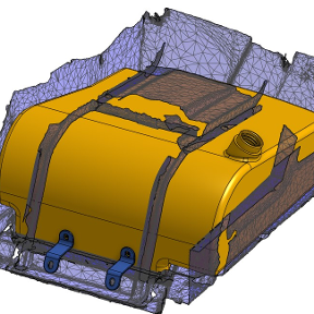
I have a hole that I wish to "mirror", but I cannot select the hole to mirror. It looks like the hole has been merged into the main "part" so I can only mirror the part, not the hole.
Can anyone explain what I am doing wrong? (It's a simple shape so I can easily replicate the hole, but I am keen to understand more, for more complicated builds!). Here's the link, the hole is obvous, and I want it mirrored to the other side of the main part:
https://cad.onshape.com/documents/993c1b88b1e294865d8a1511/w/54ab408e55c5a70bceaf3002/e/7540d5f006505e335709c195
Any help much appreciated, thank you! 😀

Re: Improvements to Onshape - August 7th, 2025
Yep, same for us. Not looking forward to having to manually reset everything!
 Matt_NC
Re: How to mirror hole?
I know this fact, but it still catches me out sometimes and leaves me head scratching before I remember it again!

Re: New Video - Project Topologies: Planning Onshape Models
@EvanReese
This is a very helpful explanation for a lot of people and small teams. I plan on sharing this with my team.
Onshape training needs to have more stuff based on real world projects/products. There are too many toy examples which don't have the complexities or constraints of actual development engineering. Hopefully in your new role you'll be able to collect more examples and learnings from multiple industries.
One thing that is important to understand about larger projects and/or teams is that a document is a unit of branching, merging and history. You rightly started splitting things into more documents as complexity grew in the projects. The reasons for that are not just performance, but also the ability for the story of a document to make sense. One of the many reasons for OTS parts to be in their own document(s) is that they are mostly going to come from imports and need a little clean up and metadata at most. OTS stuff is unlikely to branch and merge. OTS stuff is also more likely to get reused in future products/projects. It's awkward for it to be in the same document as all the custom parts which are related to a particular project.
For complex projects, subsystems often need their own document because their development path is not identical to the main product or ID. Early in development, those subsystems may be bench tested and iterated on with different concepts where branching and merging the entire project doesn't make sense.
I'm a little confused about the mentions about Super Derive and variables. Now that we have Variable studios, is Super Derive still useful and necessary for distributing variables? I'm also curious what your take is on @GregBrown 's Publish feature?
Another way I would look at this document structure topic is to review some of the things that don't work as well and why. For example, there are occasionally people that will say that every part should be its own document. For me that's completely missing the point of top-down design and collaboration possibilities, but it seems to have grown out of a fear of how release management works and how to find things. It's coming from people used to file-based CAD that haven't really understood Onshape.
Document structures also evolve over the course of a project. Early on, most/all of the project may be in a single document where rapid iterations with live workspace references are essential. As maturity and complexity grows, it makes sense for a bunch of reasons to split into multiple documents where, by definition you have to use version references. Even within the same document, there are phases of development. As things become more real and release management is essential, references need to switch from workspaces to versions/revisions.
S1mon