Welcome to the Onshape forum! Ask questions and join in the discussions about everything Onshape.
First time visiting? Here are some places to start:- Looking for a certain topic? Check out the categories filter or use Search (upper right).
- Need support? Ask a question to our Community Support category.
- Please submit support tickets for bugs but you can request improvements in the Product Feedback category.
- Be respectful, on topic and if you see a problem, Flag it.
If you would like to contact our Community Manager personally, feel free to send a private message or an email.
Best Of
Re: Configure Part Name Feature?
@EvanReese thanks for this! One issue … if you rename a part (e.g. Part1 → End1) and then apply the Part Name feature to the now-renamed part (End1), the name does not apply. I was able to reset the part to the default by going into the part's properties and clicking the Reset All button. But it seems like the feature should be able to overwrite the custom name.

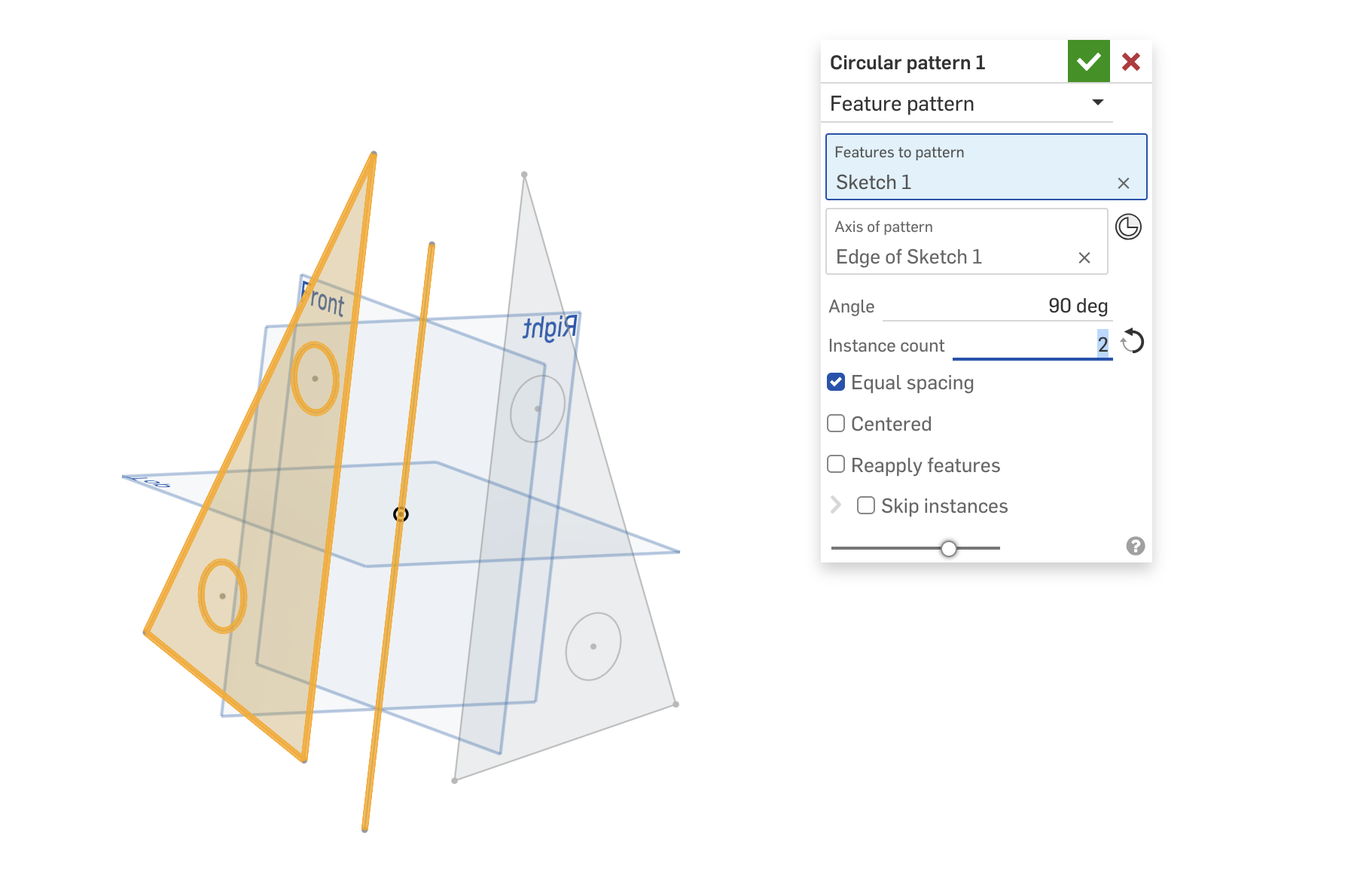
Re: How to copy a sketch by 90 degrees
Thank you, that was helpful! I wanted to copy the sketch only and I was trying the circular pattern, but I had overseen the drop down at the top to select feature pattern that I saw in your screen shot.
Now it works:
 baumar

Re: Improvements to Onshape - September 19th, 2025
Both folders and labels have benefits—even together. However, the current issue with labels is that they are user-specific. From the Onshape help:
"All labels are user-specific, and no other user sees the labels you apply to documents and publications, regardless of permissions."
https://cad.onshape.com/help/Content/labels.htm
Because of this, it dramatically reduces the utility of labels currently.

Re: Improvements to Onshape - September 19th, 2025
Right, that's why I completely gave up on making a library of labels.
It doesn't share with others, and having parts marked as library or whatever just gives a short list when others add to the library. Having a library folder made more sense since everyone always sees the same items and hierarchy.
Having the ability to have company wide labels would be a huge improvement and would help with onboarding. They would still have a full library of folders and such, but the most common items would have a label to jump directly to them.
I only label a couple odd things, like drawing blocks or something I search a lot that is deep into a folder chain. I just checked, looks like I only have 3 labels total, I think I only use 1 of those commonly
