Welcome to the Onshape forum! Ask questions and join in the discussions about everything Onshape.
First time visiting? Here are some places to start:- Looking for a certain topic? Check out the categories filter or use Search (upper right).
- Need support? Ask a question to our Community Support category.
- Please submit support tickets for bugs but you can request improvements in the Product Feedback category.
- Be respectful, on topic and if you see a problem, Flag it.
If you would like to contact our Community Manager personally, feel free to send a private message or an email.
Custom Feature: ProtoPipe – Totally tubular structures, totally fast.

Dear PiedPipers!
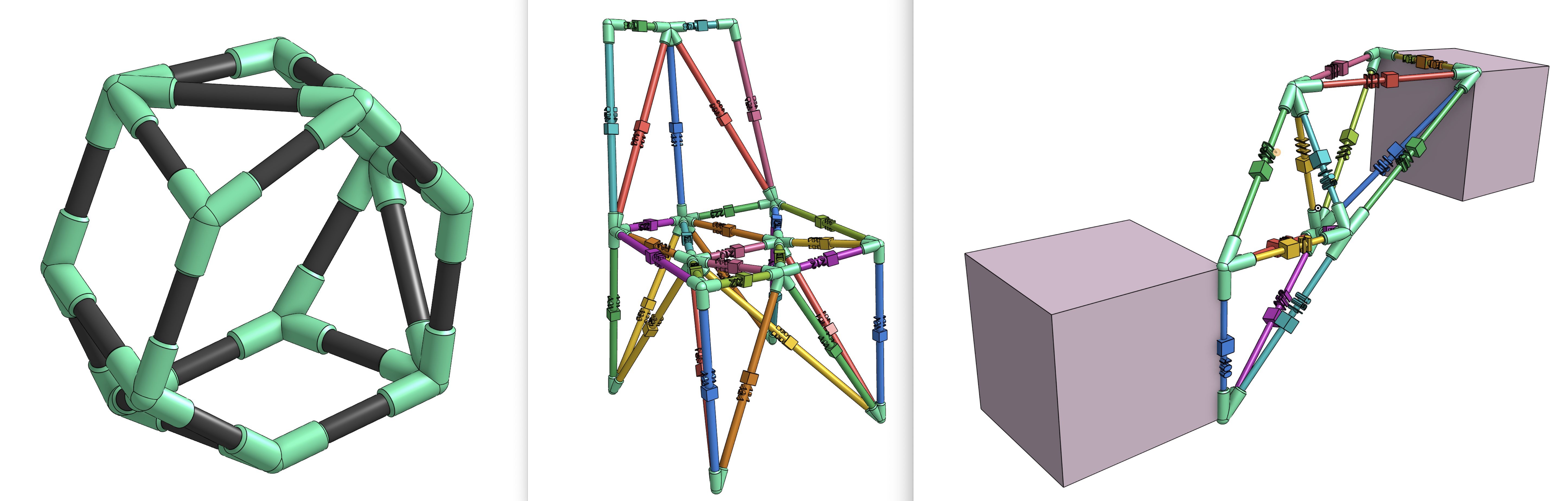
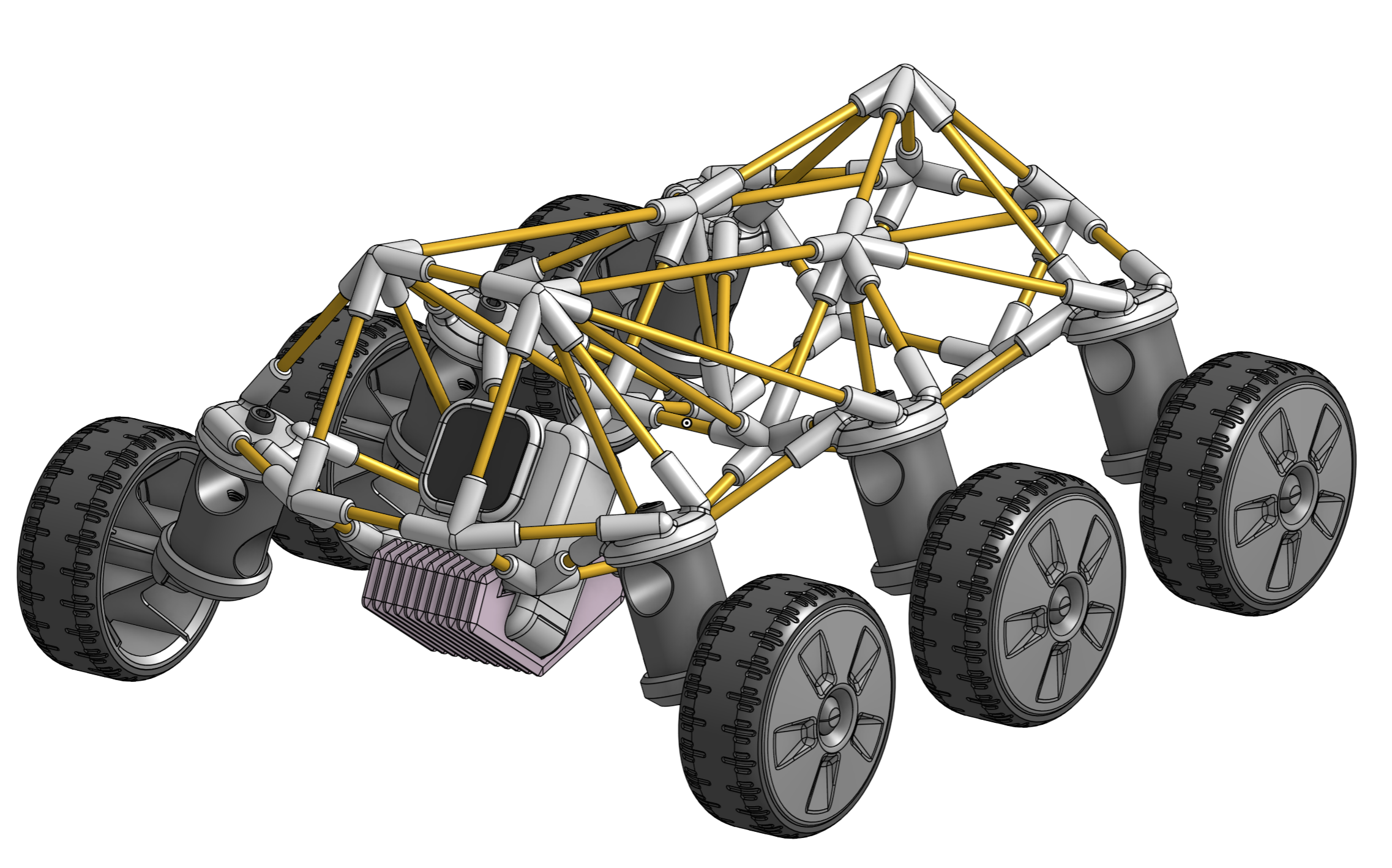
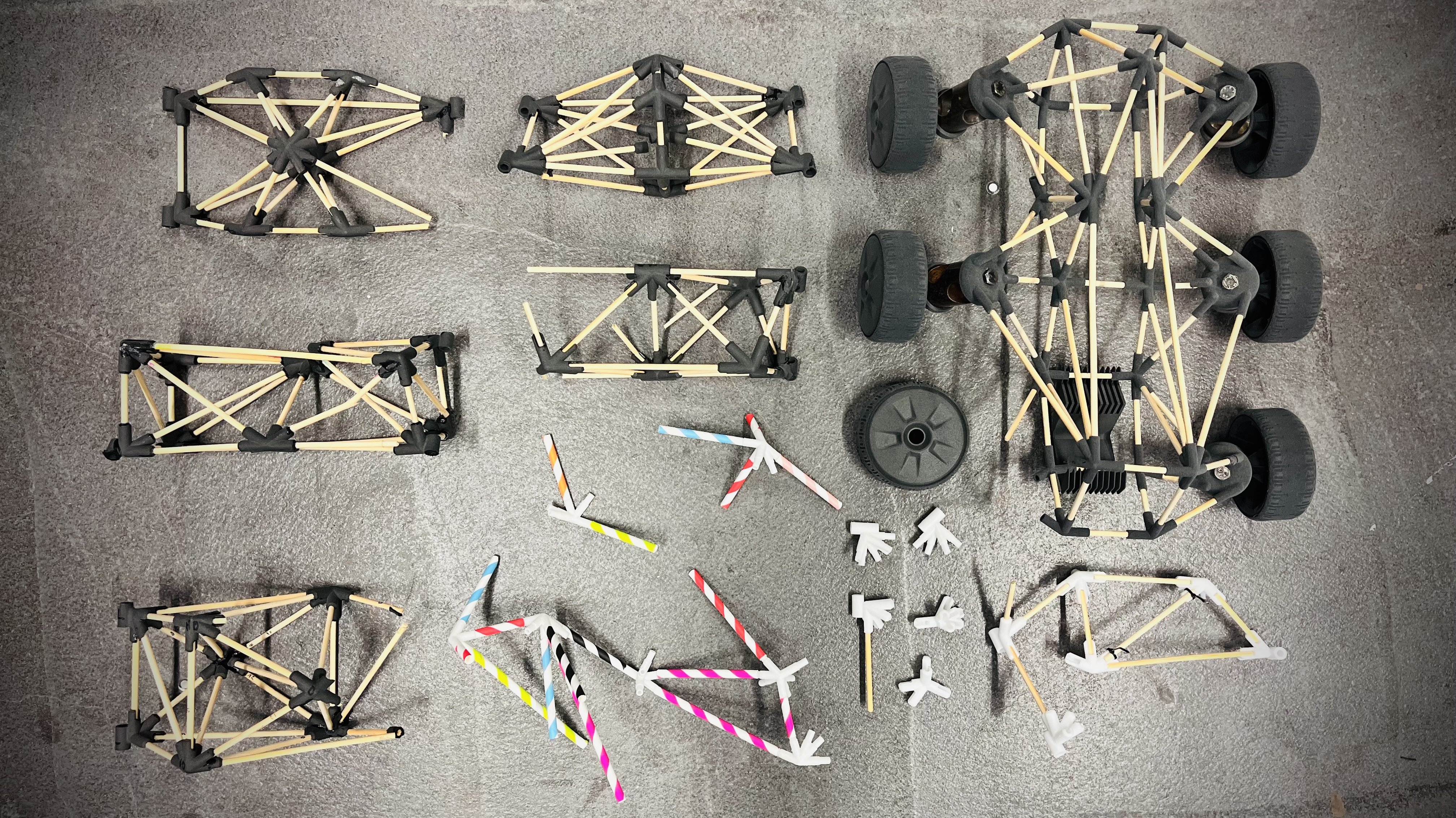
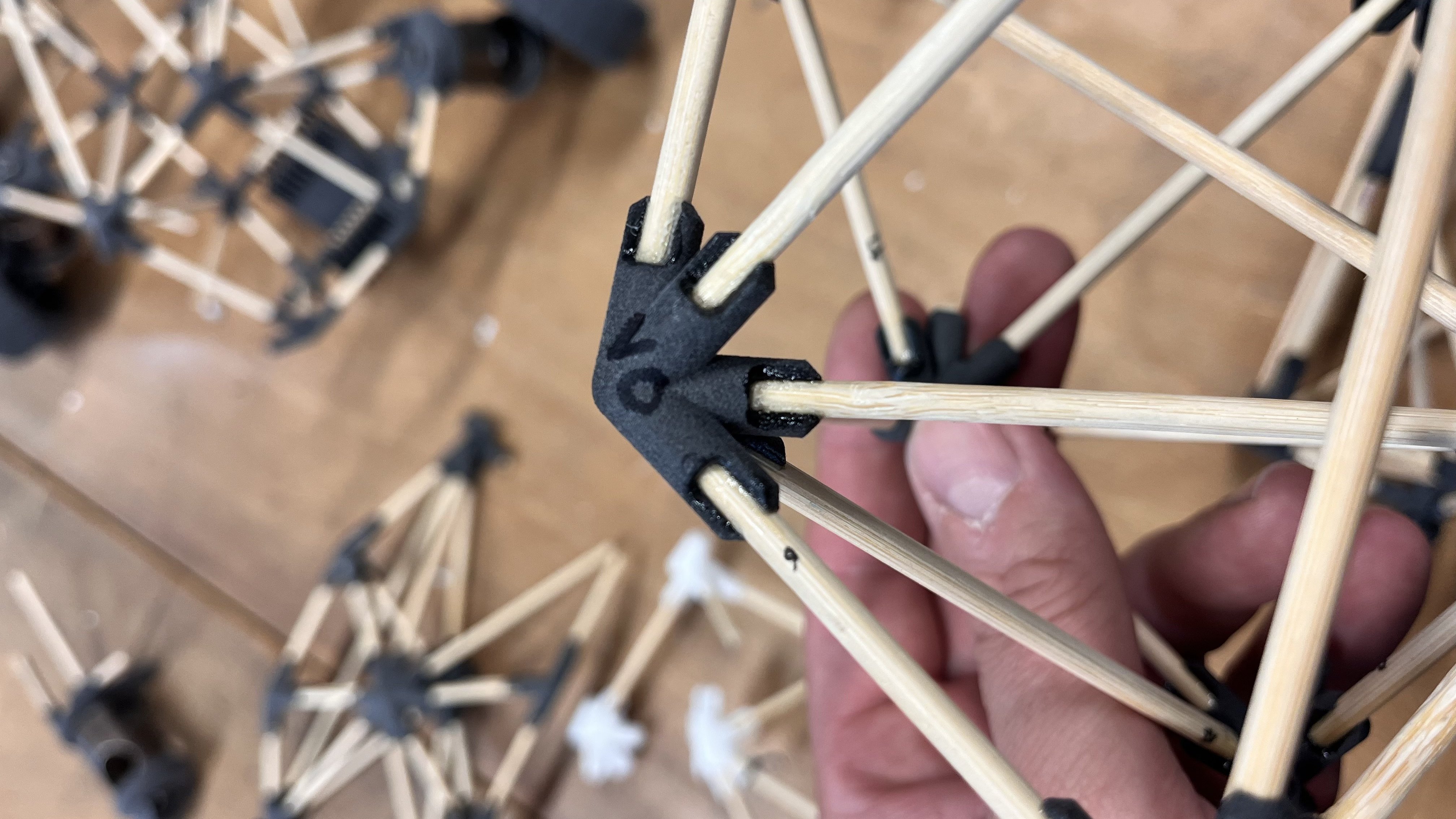
Every year, I challenge my Industrial Design students to an "intuitive engineering" contest: building bridges out of wooden sticks and 3D-printed nodes. Building these the standard way – juggling 3D-points, routing curves, queries, and pipe edges – works okay, but means a lot of going back and forth…
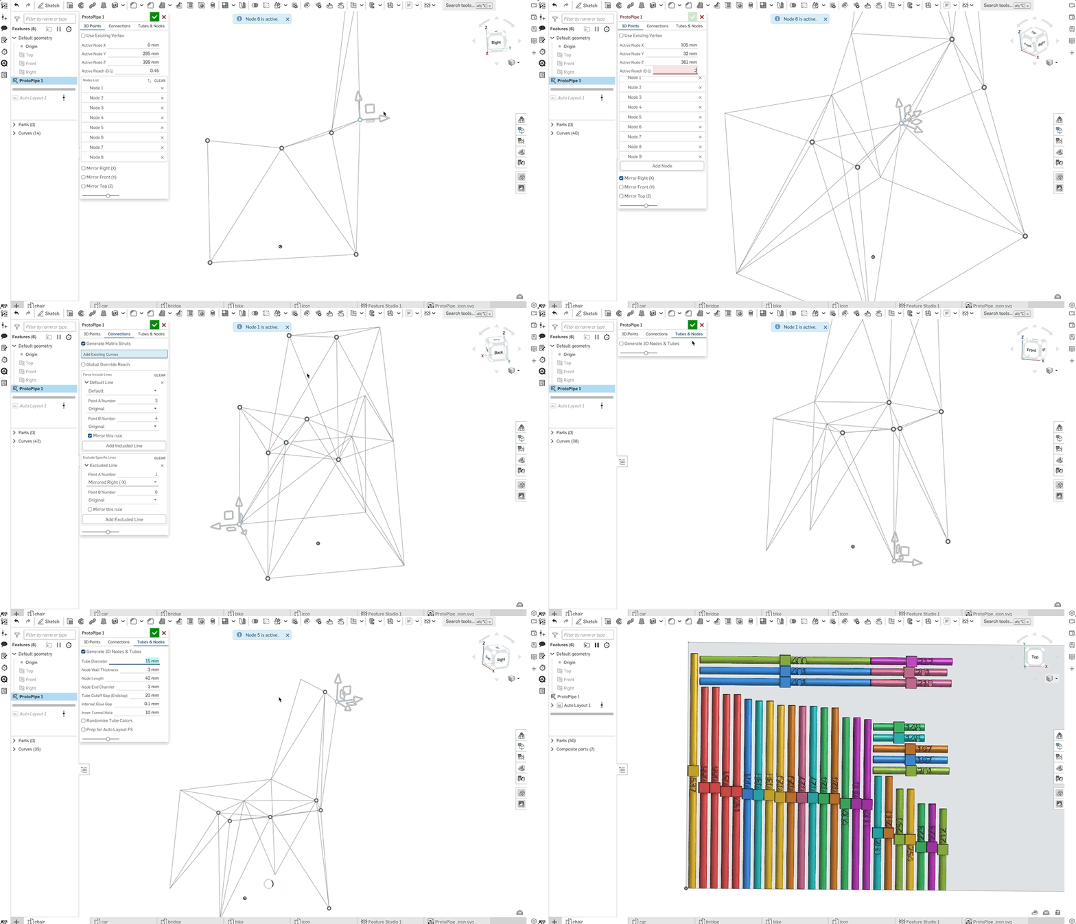
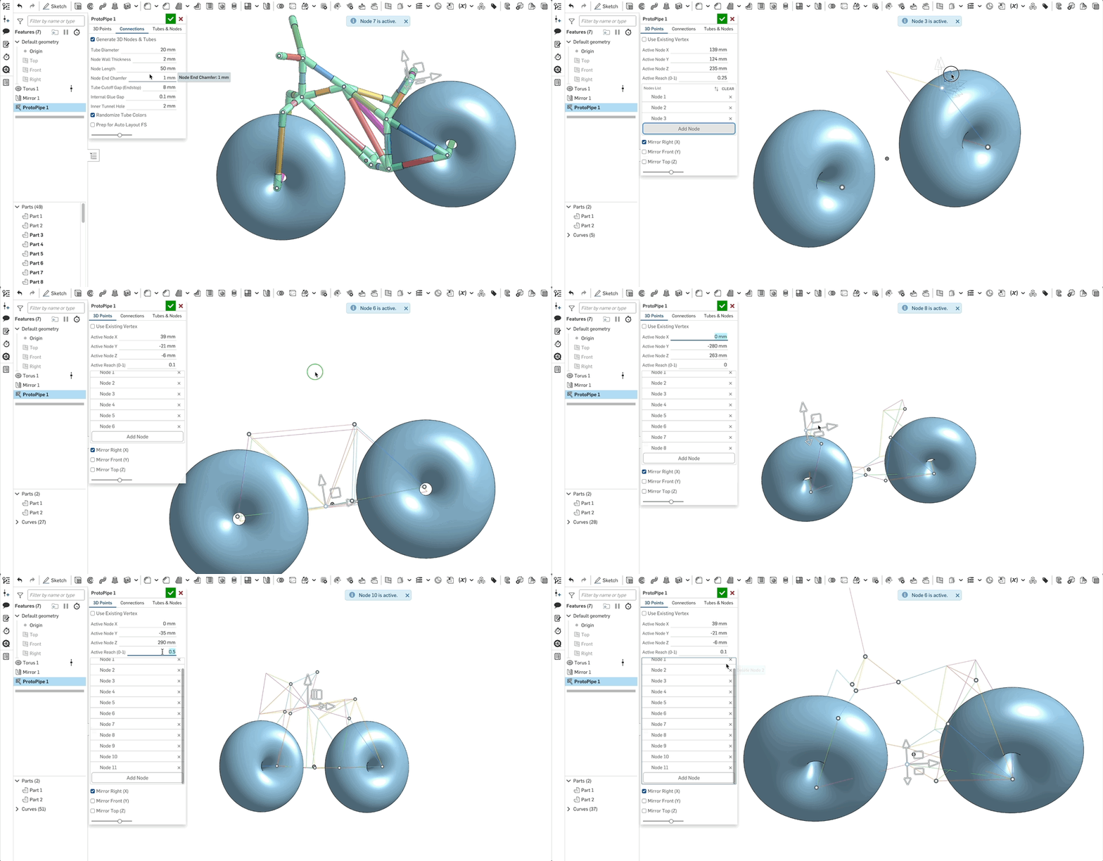
I wanted a tool that lets you drop 3D points on the fly, adjust their "Reach" to control connectivity, and instantly generate a prototype-ready structure.
Enter ProtoPipe! A fast way to design spaceframes that are easy to fabricate.
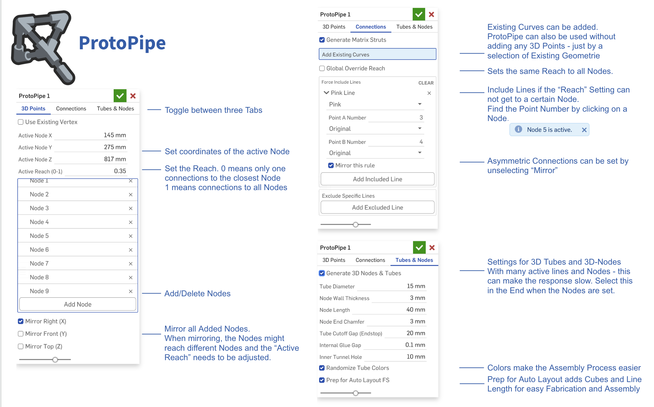
The tool is split into three simple tabs that guide you through the workflow:
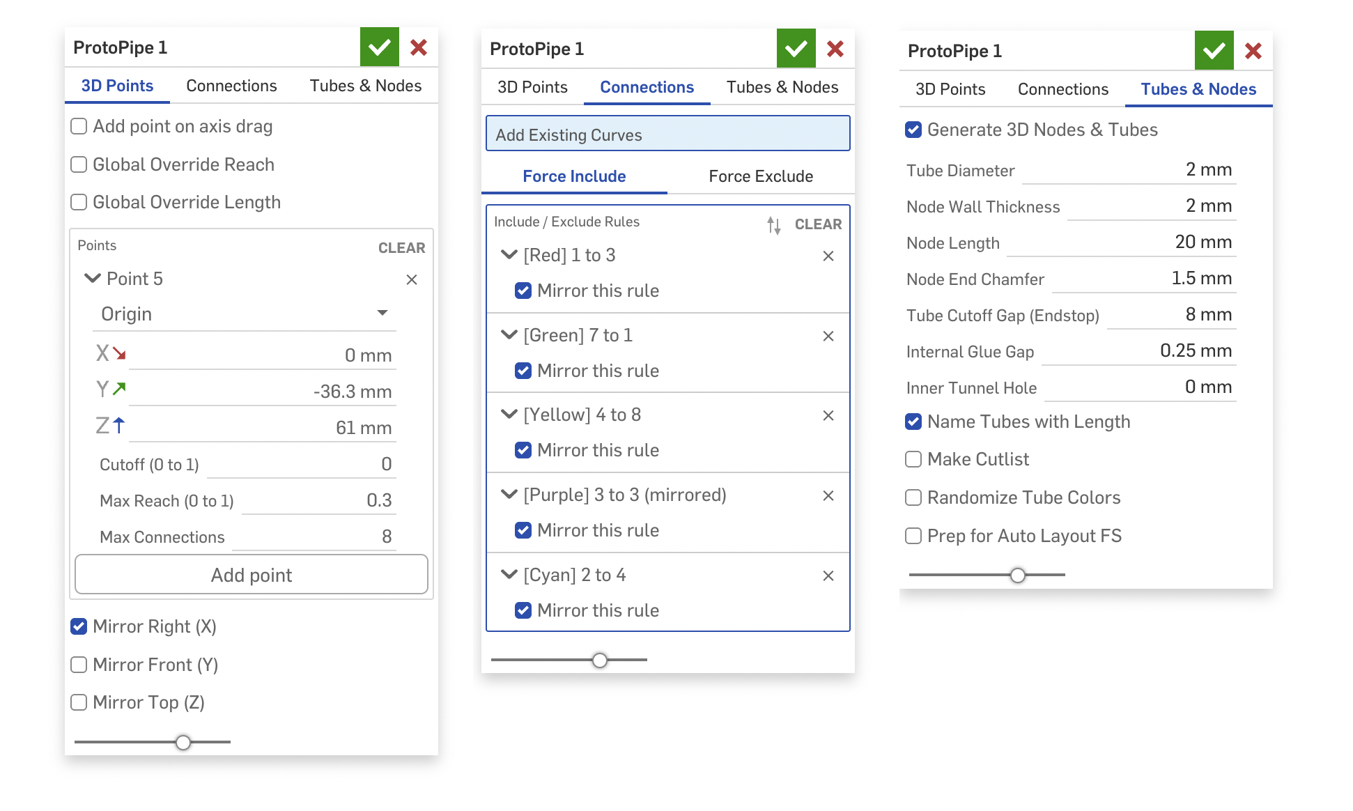
- 3D-Points: Add and tweak your points, then set the "Reach." A Reach of 0 connects only to the nearest neighbor, while a 1 connects the point to everything in sight.
- Connections: Manually include or exclude specific lines if the automatic Reach settings need a little fine-tuning.
- Tubes and Nodes: Generate the final 3D geometry. And It preps the tubes so you can easily auto-layout them for fabrication later.
I'm not entirely sure if there is a massive real-world use case for this yet, so I’d love to hear what you all think. And maybe this is a case where a classic custom feature tree still makes more sense:)
But here are a few ideas to get you started
- Go big: Build structures way larger than your printer's build volume using standard PVC pipes.
- Scavenger prototyping: Use drinking straws, dry spaghetti, broomsticks, cardboard tubes, pool noodles selfiesticks….
- Print flexibility: We use SLS printers (which are perfect for the complex nodes), but standard FDM works perfectly fine too.
- Get flexible: inflatable bike tubes could create dynamic, flexible frames.
- Snap-fit Assembly: In an older Part Studio, I had partly open nodes working so you could snap the tubes in from the side – no sliding required!
Bringing that back would mean changing the whole architecture, though...
Comments
-
-
I completely don't care how "massive real world use case" this is. This is super awesome. That's a good enough reason.
One extension that occurred to me: determine, from a catalog of joints, what the "closest" fit would be and build a nearest-fit version from that.
2 -
Thank you! You have to explain a bit more how you imagine this “catalogue of joins”…
As of now, selecting a point and setting the reach to 0 picks the closest point and makes just one connection. If there are 10 points, setting it to 0.5 will make 5 connections (from that point)… and 1 will make all connections.
Prior to this reach system, I played around with different ideas:
- generating a closed body from all the points and working with this
- defining the total number of connections that are allowed
- making more lines where the body walls are closer to each other
- I was trying to do topology optimisation without actually doing that :)
but i liked the simplicity of individual reach settings…
0 -
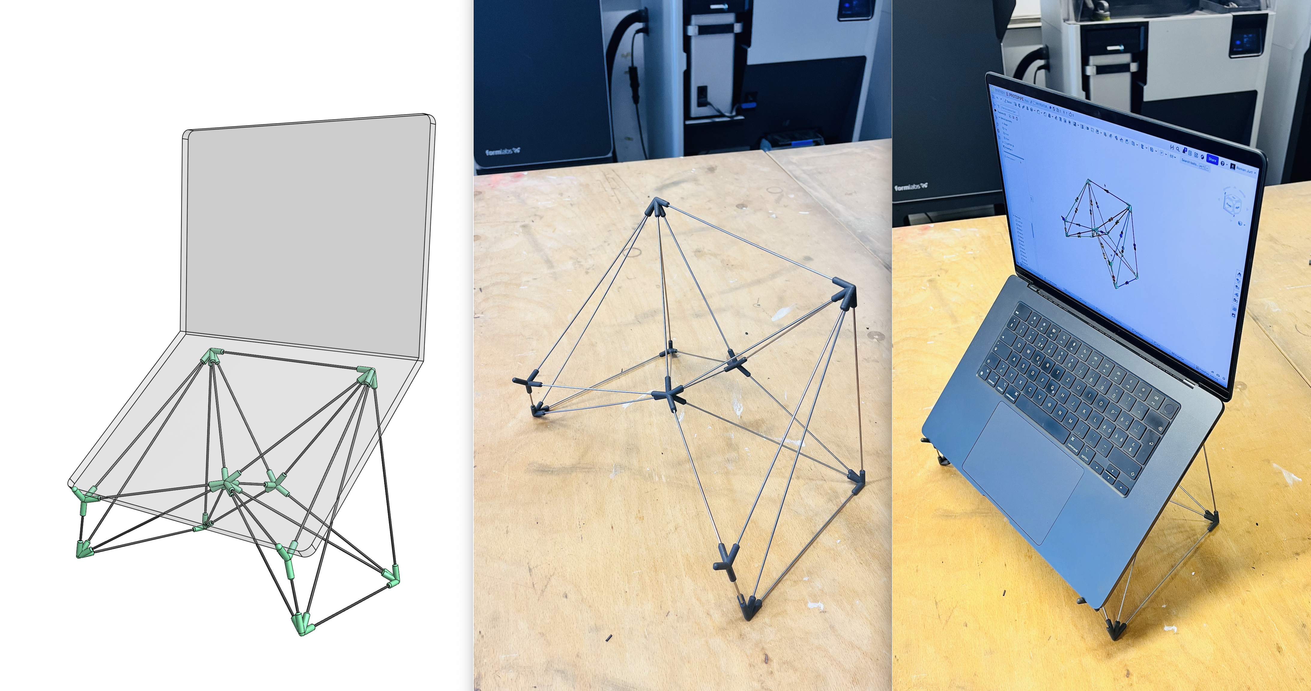
I did some real-life tests. I designed a laptop stand in 5 minutes, printed the nodes (in PA12 on your Fuse 1 printer). and cut and assembled the 2 mm stainless steel wires on the fly, using the digital model as a guide. This took me another 5 minutes.
I'm really happy with how quickly I could iterate through different ideas and node placements. The resulting structure is rigid while remaining lightweight and elegant.
I suggest unchecking "Generate 3D Nodes and Tubes" until you're satisfied with the construction, and only enabling it at the end.
 4
4 -
Wow… That's wild. nice job.
1 -
This is disgustingly cool! I recall chatting a bit about this kind of thing a while back and it's awesome to see the workflow so refined! I may have to buy a stock of little rods to keep next to my printer now.
1 -
Okay I replied before I even played with it. There's a magical (if unpredictable) amount of logic going on to automate connections with Reach which is interesting. It feels very fluid to use. It's great as-is, but in case you want some extra work here are some ideas 🙃:
- include "add point on axis drag" option like Routing Curve. It makes creation even faster. If you drag an arrow it makes a new point, if you drag a square it doesn't. It's nice not having to mouse back to the UI over and over.
- Handle nodes more like Routing Curve instead of how I did it on Freeform spline. It's better than managing a massive list of "node nth" which doesn't mean much.
- Use point manipulators for mapping connections, rather than saying point 1 to point 4. Again, trying to push the interactivity. Maybe the multi-select capability recently added to Edit Curve and Routing Curve has something to teach?
- Skip the auto-layout part and create an automatic Cutlist table instead. I don't think you're actually using Auto-layout for production, you are just trying to make an easy-to-reference collection of rods. Cutlist is the perfect solution here. It can have length and qty for each rod, as well as cross-highlight to the rods in the model when you mouse over the table. It can even be inserted into a drawing and ballooned if you wanted to just bring a 1-page drawing to the shop to make your cuts (though I'd personally just bring the iPad)
- Add "description" to all of the parameters, so users get a tooltip on mouseover. Since you're using an LLM it should be fast.
- Handle crossed beams with another joint (or at least make it optional). It's easy to produce beams that intersect one another, and for some build they might be fine to just bend past one another, but for other cases you'd want a joint there.
3 -
Thank you! And thank you @EvanReese for your ideas - very helpful ! Here are my comments:
- Yes - this makes a lot of sense. At the moment it even spawns the new node at the second-to-last location... not ideal. I'm going to implement this.
- Yeah - I think I'll just borrow the hole routing curve logic here.
- Hmm - this is what I initially wanted, but it kept crashing. I never quite understood why it was possible to enter the positions but not select them. The agent was quite convinced that there was a logic loop preventing it. I'm not happy with manually typing in points either. And when adding a lot of includes/excludes, it also becomes quite hard to find them... hence the color add-on.
- I was also thinking about a cut list, and sure, it's neat. But being able to navigate through the tubes in the graphics area while assembling and see the length written directly on the tube is quite nice. I think selecting a frame part will not highlight the corresponding cut-list entry. I'm trying to avoid creating a drawing altogether :) But maybe I could engrave the length and add the cut list as well...
- Easy enough.
- Yeah - crossed beams will become a problem with thicker tubes. Hmm. Automatically adding a joint could be cool, but it could also make things much more complex. With a hopefully better connection setup, selecting mirrored points and excluded lines should become easier as well. And I think it already does a good job of not mirroring points that lie on the mirror plane when mirroring is enabled.
What do you think could be nice add-ons in terms of reach? Maybe the number of connections as a parameter? For example, "3 connections within a reach of 0.5". Or perhaps a minimum and maximum reach, so it doesn't connect below or above a threshold?
What about additional node features? A cutout that allows tubes to be inserted from the side? Recesses for cable ties? Screw holes? Multipart clamshell nodes (although that's probably quite challenging)? Fully rounded nodes? (I tried that manually and it also seems difficult :) )
 0
0 -
I would recommend looking at Cutlist+. It will rename the frame parts based on frame profile and length. Cross highlighting works well too.
https://cad.onshape.com/documents/3ef342976bcbf59ab1fab2a0/v/8b262eacecdb724faac26890/e/7707d784b4c580d8122f592cSimon Gatrall | Product Development, Engineering, Design, Onshape | Ex- IDEO, PCH, Unagi, Carbon | LinkedIn
1 -
thanks simon! i will have a look!
0 -
OK! New version – the point-selection UI is now the same as the routing curve. It feels quick and very intuitive. I like it a lot. I also added a cutoff value (where the shortest connections get cut off).
There are quite a few improvements in the connections tab as well. You can toggle between include or exclude, and when you click two points, a new line gets generated or an existing line disappears. I couldn't get the classic selection box to work (apparently, it's impossible for a Query selection box to resolve to entities created by the active feature itself during the editing phase), but my workaround with colored lines and selected dots turning green works well too.
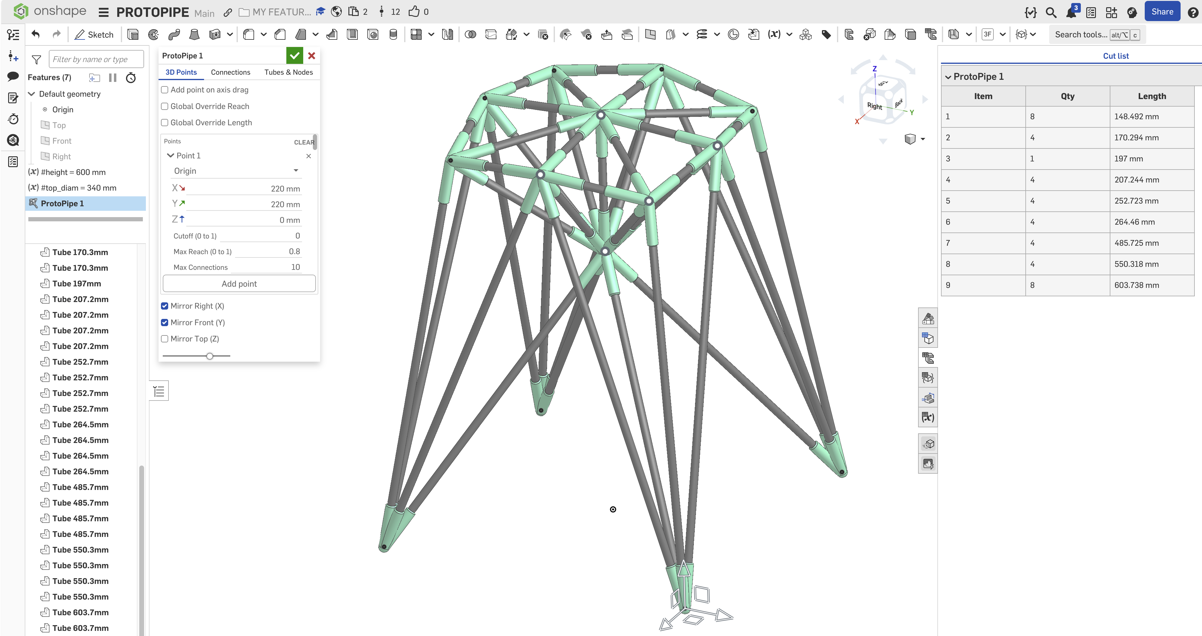
I also implemented a cutlist, an option to name the parts with their length, and some other smaller things and tooltips :)
I tested it, and I really like the interactions that let you iterate and try different layouts in seconds! And when assembling, selecting a tube highlights the tube length in the parts list – quite comfortable.
 3
3 -
This is shaping up nicely!
It would be neat to be able to input multiple mate connectors or vertices as a single query for more dynamic or configurable generation.
Perhaps each group of queries could represent connections, so that connections could be automated all in one go.Here's an example of how to do it.
◉ RENDERCAD - Photorealistic product rendering.◉ CADSharp - Professional CAD + software consulting.
▚▞▚▞▚▞▚▞▚1 -
This is looking great! I'll play with it when I get a chance. I like the idea of the snap in nodes, but at this point I'd like to remind you that this is just one feature in the tree, and making a do-everything feature is a trap. You could create a second feature that does follow up things. For example, you might tag each node with attributes that identify it as a node and include a vector for the next feature to make into a point manipulator. Then the next feature, Modify Node, lets you multi-select them and change their settings. Maybe a few of them need snap-in connections, or some should be thicker walls, etc. I could even see a followup feature that handles the crossed struts after the fact if you can't find a good algorithmic solution that requires no human judgement. The only issue I can see with followup features is potential for very unstable IDs for struts and nodes, but maybe that can be handled.
1 -
Hey @MichaelPascoe, thanks for your idea and link! But i think Evan is right about the do-everything thing... this was meant to be a "prototyping" tool... drag points around, figure connections out in a playful way... then print, assemble... if I stuff too many production things in it – it might become less easy and intuitive... don't you think Or maybe you have a usecase in mind that still fits the ProtoPipe vibe for your idea?
0 -
@EvanReese Thank you! Adding some helpers to a later process would probably be a good thing... I tried to subtract retaining rings and clips onto each node... but couldn't even get a query variable to work with the nodes (I tried matching, circle, arc, surface...). They are geometrically all the same, in wild orientations... but the same. And query pattern was not very helpful therefore either :)...
Here are my tests - if a query expert would like to try :)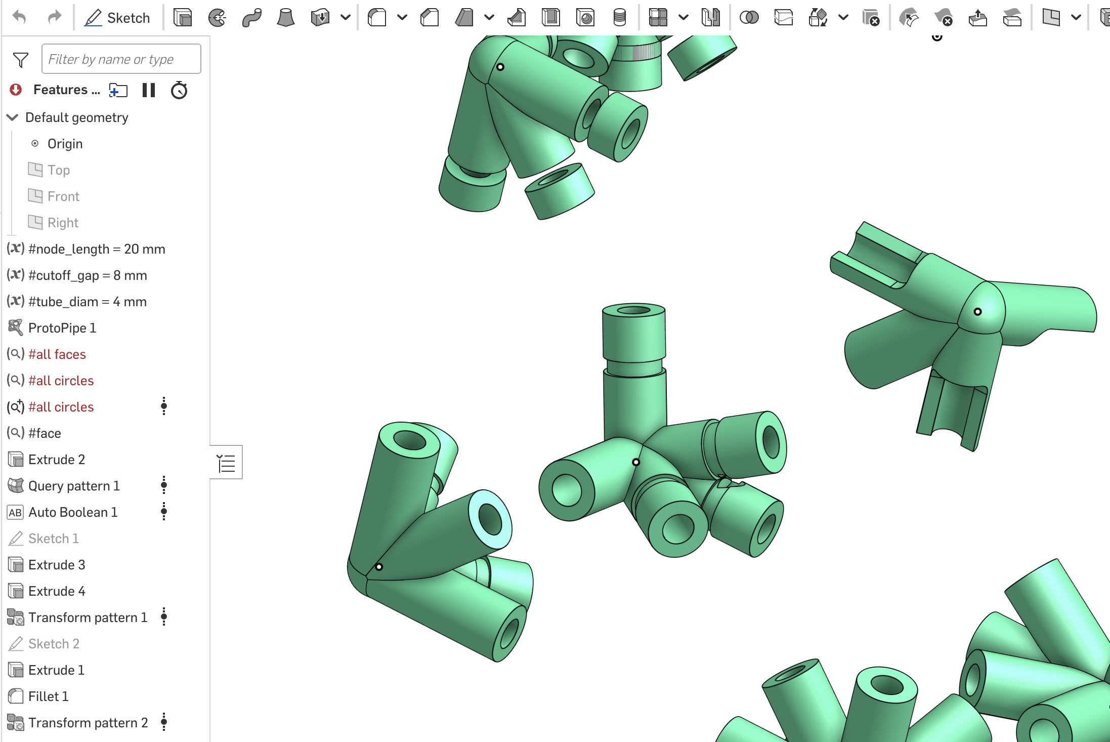 0
0 -
@roman_jurt190 The Protopipe feature can declare as many query variables as you want it to, rather than doing them with the actual Query Variable feature. That'll be way more powerful and convenient. Even that could be a second feature if you want it to, by querying all of the things you may later care about in the main feature, then applying attributes to them. The downstream feature could re-query them via attributes, and declare them as query variables. I imagine a Protpipe Queries feature which is a feature reference param to pick which Protopipe feature made the stuff, then a bunch of checkboxes for the queries so you don't have to include them all. That way the main feature UI isn't bloated with a bunch of options for Query Variable output, and the Query Variable list isn't polluted with a bunch of queries no one cares about. You could also add an optional string param to prepend the variable names.
0