Welcome to the Onshape forum! Ask questions and join in the discussions about everything Onshape.
First time visiting? Here are some places to start:- Looking for a certain topic? Check out the categories filter or use Search (upper right).
- Need support? Ask a question to our Community Support category.
- Please submit support tickets for bugs but you can request improvements in the Product Feedback category.
- Be respectful, on topic and if you see a problem, Flag it.
If you would like to contact our Community Manager personally, feel free to send a private message or an email.
Custom Feature: ProtoPipe – Totally tubular structures, totally fast.
 roman_jurt190
Member Posts: 79 EDU
roman_jurt190
Member Posts: 79 EDU
Dear PiedPipers!
Every year, I challenge my Industrial Design students to an "intuitive engineering" contest: building bridges out of wooden sticks and 3D-printed nodes. Building these the standard way – juggling 3D-points, routing curves, queries, and pipe edges – works okay, but means a lot of going back and forth…
I wanted a tool that lets you drop 3D points on the fly, adjust their "Reach" to control connectivity, and instantly generate a prototype-ready structure.
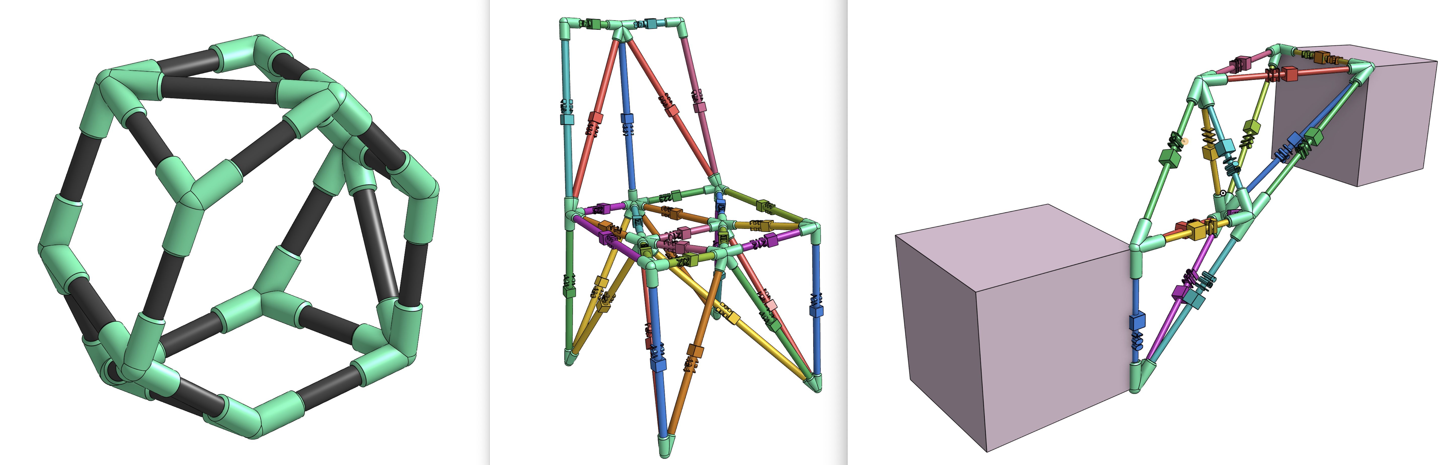
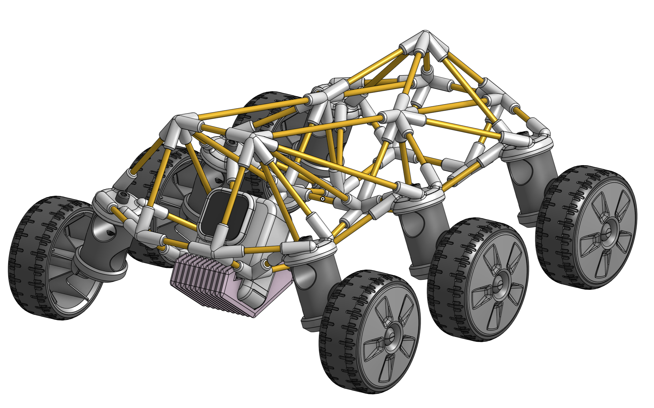
Enter ProtoPipe! A fast way to design spaceframes that are easy to fabricate.
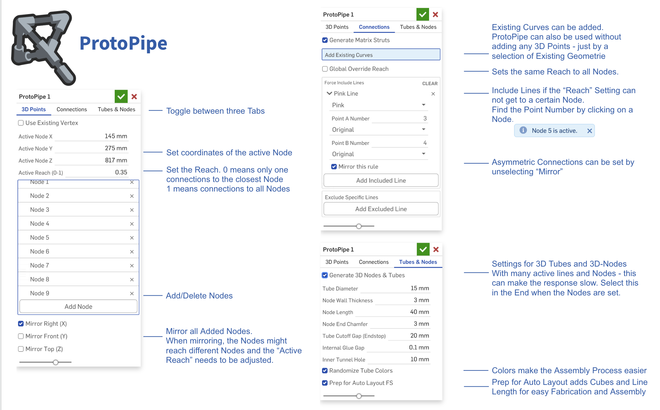
The tool is split into three simple tabs that guide you through the workflow:
- 3D-Points: Add and tweak your points, then set the "Reach." A Reach of 0 connects only to the nearest neighbor, while a 1 connects the point to everything in sight.
- Connections: Manually include or exclude specific lines if the automatic Reach settings need a little fine-tuning.
- Tubes and Nodes: Generate the final 3D geometry. And It preps the tubes so you can easily auto-layout them for fabrication later.
I'm not entirely sure if there is a massive real-world use case for this yet, so I’d love to hear what you all think. And maybe this is a case where a classic custom feature tree still makes more sense:)
But here are a few ideas to get you started
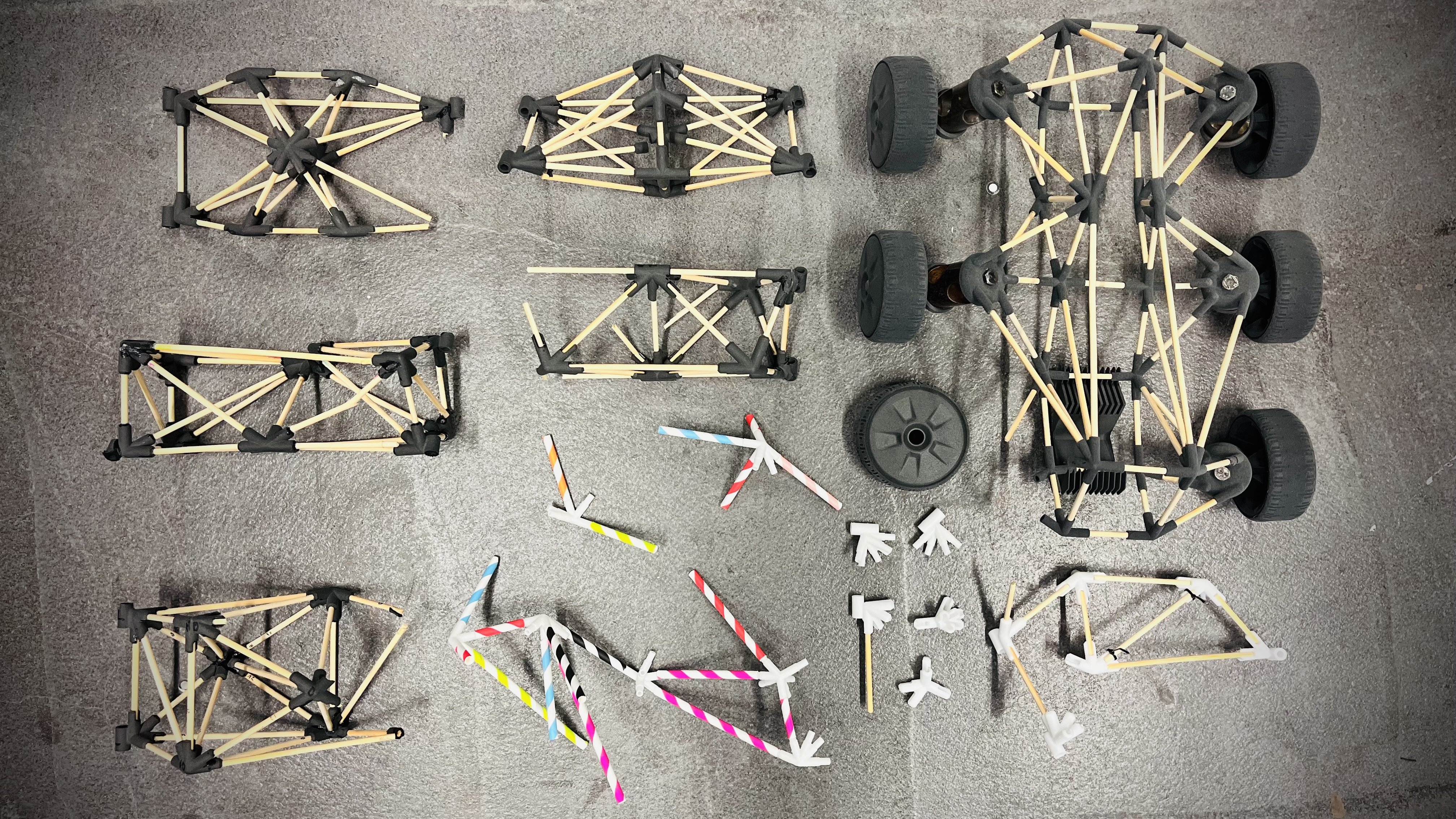
- Go big: Build structures way larger than your printer's build volume using standard PVC pipes.
- Scavenger prototyping: Use drinking straws, dry spaghetti, broomsticks, cardboard tubes, pool noodles selfiesticks….
- Print flexibility: We use SLS printers (which are perfect for the complex nodes), but standard FDM works perfectly fine too.
- Get flexible: inflatable bike tubes could create dynamic, flexible frames.
- Snap-fit Assembly: In an older Part Studio, I had partly open nodes working so you could snap the tubes in from the side – no sliding required!
Bringing that back would mean changing the whole architecture, though...
Comments
Ooo! 🤩
RENDERCAD
rendercad.ai - Photorealistic product rendering.
▚▞▚▞▚▞▚▞▚
________________________________________________________________________
I completely don't care how "massive real world use case" this is. This is super awesome. That's a good enough reason.
One extension that occurred to me: determine, from a catalog of joints, what the "closest" fit would be and build a nearest-fit version from that.
Thank you! You have to explain a bit more how you imagine this “catalogue of joins”…
As of now, selecting a point and setting the reach to 0 picks the closest point and makes just one connection. If there are 10 points, setting it to 0.5 will make 5 connections (from that point)… and 1 will make all connections.
Prior to this reach system, I played around with different ideas:
but i liked the simplicity of individual reach settings…
I did some real-life tests. I designed a laptop stand in 5 minutes, printed the nodes (in PA12 on your Fuse 1 printer). and cut and assembled the 2 mm stainless steel wires on the fly, using the digital model as a guide. This took me another 5 minutes.
I'm really happy with how quickly I could iterate through different ideas and node placements. The resulting structure is rigid while remaining lightweight and elegant.
I suggest unchecking "Generate 3D Nodes and Tubes" until you're satisfied with the construction, and only enabling it at the end.
Wow… That's wild. nice job.
This is disgustingly cool! I recall chatting a bit about this kind of thing a while back and it's awesome to see the workflow so refined! I may have to buy a stock of little rods to keep next to my printer now.
The Onsherpa | Reach peak Onshape productivity
www.theonsherpa.com
Okay I replied before I even played with it. There's a magical (if unpredictable) amount of logic going on to automate connections with Reach which is interesting. It feels very fluid to use. It's great as-is, but in case you want some extra work here are some ideas 🙃:
The Onsherpa | Reach peak Onshape productivity
www.theonsherpa.com