Welcome to the Onshape forum! Ask questions and join in the discussions about everything Onshape.
First time visiting? Here are some places to start:- Looking for a certain topic? Check out the categories filter or use Search (upper right).
- Need support? Ask a question to our Community Support category.
- Please submit support tickets for bugs but you can request improvements in the Product Feedback category.
- Be respectful, on topic and if you see a problem, Flag it.
If you would like to contact our Community Manager personally, feel free to send a private message or an email.
Optimizing an unsupported screw hole for a 3D printed enclosure

mauronic
Member Posts: 9 ✭✭
I have a hole for an M3 screw and I simply ran a column from the top of my enclosure to the bottom. Obviously not ideal. I would like to model something that receives a short screw and then tapers at < 45 degree angle to the sides. This will save a little material, weight and reduce print time.
I am having a problem elegantly constraining the bit to the corner as well as tapering it. In other words, it's offset and too long now. I guess I could create a shape and do a 90 degree revolve but I am looking for ideas for the most elegant solution.
Hope this makes sense. I can share my drawing if that helps. Not sure if sharing publicly is view only.
pete
I am having a problem elegantly constraining the bit to the corner as well as tapering it. In other words, it's offset and too long now. I guess I could create a shape and do a 90 degree revolve but I am looking for ideas for the most elegant solution.
Hope this makes sense. I can share my drawing if that helps. Not sure if sharing publicly is view only.
pete
0
Answers
-
hey Pete, I'm all for optimization, but in this case your time spent on this problem will far outweigh the material cost or manufacturing time difference from using your method. I would urge you to just connect it to the walls and be done with it.
 0
0 -
Here's how I would do it. Hope it helps https://cad.onshape.com/documents/14a5470145a0454ea422679c/w/dd736aa19c404c94bddf2f400
-
So maybe my rationale for fixing this wasn't captured well... I am a noob and maker so. When I have an idea like this in my head and am not sure how to execute it, it is really helpful for me to see how someone else would approach it. In this case I learned a couple of things already.Onshaper said:hey Pete, I'm all for optimization, but in this case your time spent on this problem will far outweigh the material cost or manufacturing time difference from using your method. I would urge you to just connect it to the walls and be done with it.
Thanks for taking the time to sketch and share and turning me on to projection which which I will have to experiment with. I was actually interested in tapering the whole thing about 10-15mm from the top so nothing wold go through to the bottom. See pic.Onshaper said:Here's how I would do it. Hope it helps https://cad.onshape.com/documents/14a5470145a0454ea422679c/w/dd736aa19c404c94bddf2f400 -
@Mauronic Are you going to have this injection molded. If you are the mold for the way you would like to have it made is going to add a lot of $$ to the cost of your mold. Molds do not deal with negative draft well. The example that @Onshaper gave will mold with out problems.
If this is going to be cast in metal again there is a problem with negative draft.
If You are going to 3D print the part the corners will be stronger with corners as @Onshaper example.
DaveDavid Sohlstrom
Ariel, WA0 -
I managed to do
https://cad.onshape.com/documents/82aebba0966b445db58af166/w/3a0ab869c6644b0390969263/e/32753111666f47ea9e538385
that is closer, right?
I know it's not perfect, but it should be very 3D printer friendly
edit: added second one into the same model, now i think it should be almost exactly what you want
1 -
@Mauronic Here's a couple approaches for you. One quick using your 90 degree revolve, one a little more optimized using a sweep.
I took the 2.5mm wall thickness as a constraint; one might be able to do interesting things with an open hole...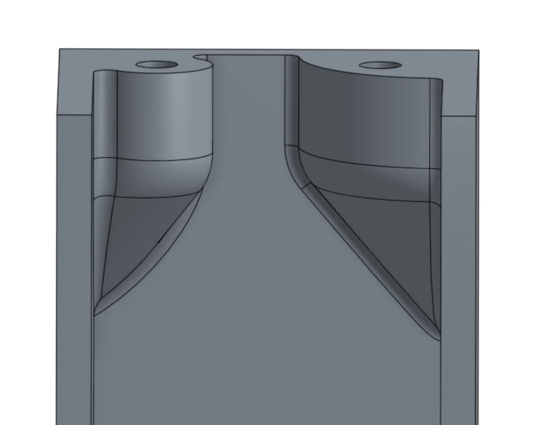
https://cad.onshape.com/documents/3a83fc705ab24c77907c79d7/w/792043e2de8e4d64b5dc1a86/e/de1d84a3931e46cb8e075ddd
0