Welcome to the Onshape forum! Ask questions and join in the discussions about everything Onshape.
First time visiting? Here are some places to start:- Looking for a certain topic? Check out the categories filter or use Search (upper right).
- Need support? Ask a question to our Community Support category.
- Please submit support tickets for bugs but you can request improvements in the Product Feedback category.
- Be respectful, on topic and if you see a problem, Flag it.
If you would like to contact our Community Manager personally, feel free to send a private message or an email.
Options
Selecting origin for In-Context created parts and mating them
 nplan
Member Posts: 2 ✭
I often find myself in a situation, where I need to create a new part in-context, but there are no pre-existing features that could be used as origin of the new part studio.
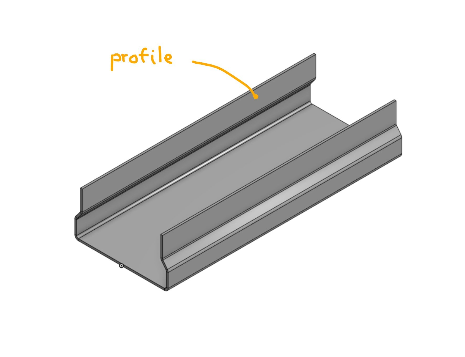
Like in this example: I have a profile:

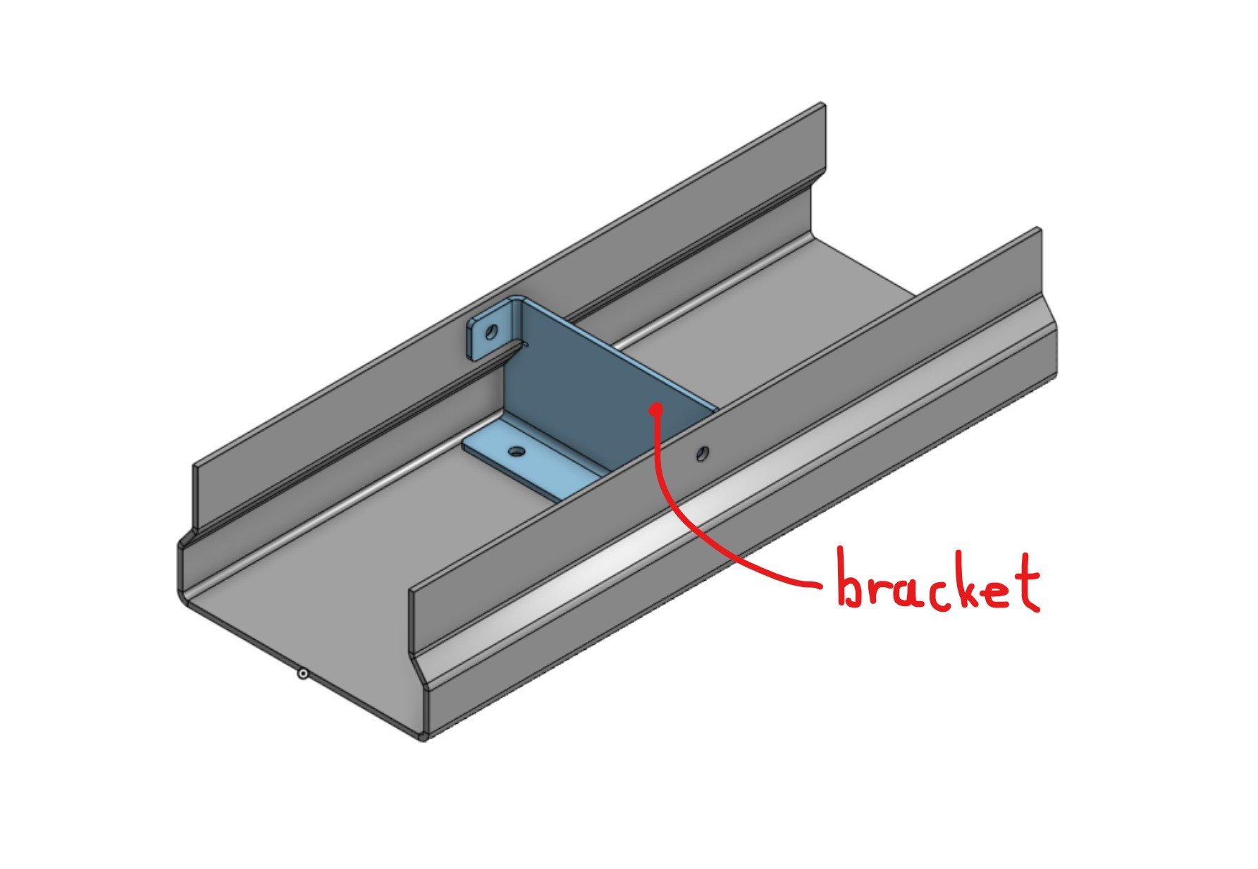
Inside it I need to put a bracket:

The bracket must fit snuggly into the profile so it's designed in-context. It must be positioned at a certain length from front end of the profile, but this length is expected to change in the future. The bracket is modeled first and then the mounting holes in profile are added last as an in-context edit referencing the bracket.
The question is first how to choose the origin of the in-context created part studio and second how to mate the bracket to the profile?
There are many ways but I feel like none of them is the "correct" one. Let's say modeling both parts in one multi-part part studio is not an option since I need this to scale to complex assemblies with many parts.
I tried this options so far: (documents for options 1 & 2 are linked, mate options A-D are created as branches in each document)
Option 1: Create part studio in-context at assembly origin. (document here)
Option 2: Create a new sketch-driven mate connector on profile part and use it as origin for in-context bracket part studio. (document here)
Fixing the parts is not an option because it's limited to current assembly and doesn't propagate to higher level assemblies.
This leaves us with 3 options, each with it's own problems:

Like in this example: I have a profile:

Inside it I need to put a bracket:

The bracket must fit snuggly into the profile so it's designed in-context. It must be positioned at a certain length from front end of the profile, but this length is expected to change in the future. The bracket is modeled first and then the mounting holes in profile are added last as an in-context edit referencing the bracket.
The question is first how to choose the origin of the in-context created part studio and second how to mate the bracket to the profile?
There are many ways but I feel like none of them is the "correct" one. Let's say modeling both parts in one multi-part part studio is not an option since I need this to scale to complex assemblies with many parts.
I tried this options so far: (documents for options 1 & 2 are linked, mate options A-D are created as branches in each document)
Option 1: Create part studio in-context at assembly origin. (document here)
- Mate option A: fix the bracket
- Mate option B: group bracket and profile
- Mate option C: fasten bracket hole to profile hole
- Mate option D: create a mate connector on bracket part at its origin (can be far away from actual part) and fasten the bracket using this mate connector to assembly origin
Option 2: Create a new sketch-driven mate connector on profile part and use it as origin for in-context bracket part studio. (document here)
- Mate option A: fix the bracket
- Mate option B: group bracket and profile
- Mate option C: fasten bracket hole to profile hole
- Mate option D: create a mate connector on bracket part at its origin and fasten the bracket using this mate connector to sketch-driven mate connector on profile
Fixing the parts is not an option because it's limited to current assembly and doesn't propagate to higher level assemblies.
This leaves us with 3 options, each with it's own problems:
- 1B - if you suppress the group and accidentally move the bracket there is no other way to reposition it other than deleting it and reinserting it. Unfortunately this breaks the references of profile holes.
- 1D - origin of part studio can be very far from the actual part. If you have a complex assembly you get a large number of mate connectors positioned at its origin which can become confusing.
- 2D - the position of bracket is now defined in a sketch inside the profile part studio. This can be very confusing when coming back later or if someone else is editing the design.
Tagged:
0
Comments
Can you create an assembly mate connector on the profile face at the top edge and offset by an amount, then create the part in-context using that? Then if you create a mate connector on the origin of the in-context part (in the Part Studio) then you have two mate connectors to fasten together.
Why not sketch both the bracket and the profile inside a "Skeleton Sketches" document, so they fit together. And then reference those?
Top level assy
-Sub 1 inside of it
-Sub 2 inside of it.
All is good.
Then I create a new document with a new assembly tab. I put in 3 of the top level assy's to this same document. (Lets say to see qty 3 of the product I'm developing side by side). Now in this new assy document, the sub1 and sub2 don't stay tied in position to the top level assy.
I think the root issue is the Fix.
And a followup, if Fix is not good, why is it in all the training?
And a further followup, is there a training document that shows a way other than Fix? I think I did all of the assembly self paced training courses but I don't recall this.
Thanks
As an alternative to fixing multiple parts, use Group or regular fastened mates instead. Group also has the additional benefit of maintaining the relative position of parts in the group - if parts are designed together in the same part studio and grouped together in the assembly, moving one part in the part studio will result in a corresponding shift in the assembly, so the parts will always be in a position which matches the part studio.
You're absolutely right. Multi-part part studios are great! Though I tend to use them for more closely related parts, 2-3 parts per part studio at max. Otherwise I find the feature tree quickly becomes too complicated and regeneration time too slow. If I have many parts that only have fixing holes in common I think in-context design is a better option. Could you elaborate on your approach a bit more?
I completely agree, I'm definitely over complicating things. But I like to think about different ways to do things in Onshape. It's great training to become an expert quickly.
Here's an example of how my robotics team applied these principles to our 2021 VEXU robot.
Geometry Sketches:
Rollers:
Intake:
As you can see, we basically created a set of sketches and/or surfaces defining the major features of the robot, in this case the outer boundary, the rollers, rear rails, and so on. Individual designers could then derive these sketches into their sketch and use them to drive their design. We also created a set of surfaces representing the major structural elements of the robot in order to make mounting and/or checking for interferences easier.