Welcome to the Onshape forum! Ask questions and join in the discussions about everything Onshape.
First time visiting? Here are some places to start:- Looking for a certain topic? Check out the categories filter or use Search (upper right).
- Need support? Ask a question to our Community Support category.
- Please submit support tickets for bugs but you can request improvements in the Product Feedback category.
- Be respectful, on topic and if you see a problem, Flag it.
If you would like to contact our Community Manager personally, feel free to send a private message or an email.
Auto Layout updated to V3.1: oriented parts!

 Added an option per some forum requests to allow specified orientation of parts. Parts will still need to be of equal thickness, but for all parts of a given thickness selecting a face as a "face to orient" will ensure that face is nested facing downwards, allowing for 2.5- or 3-axis machining on a router. All parts without a selected face to orient will be nested with the largest face down. This is a slight modification from the previous operation of this feature to facilitate use without too many manual selections when making routed parts. If the largest-face-upwards functionality is critical you may wish to keep this feature at its previous version.
Also fixed a small bug in the bin-packing algorithm, which in certain unfortunate combinations of parts could lead to part spacing constraints being violated.
Find it here: https://cad.onshape.com/documents/576e01dbe4b0cc2e7f46a55d/v/731e73ac0b7b1e4334f13106/e/b72c231628b5affea0873222
PhD, Mechanical Engineering, Stanford University
Comments
-
@lemon1324 this is great! Thanks for posting!. All of this is far beyond my FS capabilities, but how tricky would it be to add a control for grain direction? The ability to rotate selected parts 90 degrees (or perhaps an arbitrary angle) would be amazing.1
-
Should be pretty straightforward, actually.
I'm currently working on a different joint script, but I'll add this to the list of improvements to make eventually.Arul Suresh
PhD, Mechanical Engineering, Stanford University3 -
Thank you Mr Suresh! Adding grain direction control on a "per-part" basis would be a fantastic addition! Thanks again for sharing this very useful FS.0
-
Legit!
RENDERCAD
rendercad.ai - Photorealistic product rendering.
▚▞▚▞▚▞▚▞▚
________________________________________________________________________0 -
Such a great update. Assigning oriented faces saves lives

Grain direction feature could be excellent. Maybe direction of grain could be determined by selecting edges of partsHead of Technical Design @ www.yeswecan.lv
1 -
can you add an option to not put a kerf around the outside of the part?
example, a part that's 3/4"x3/4" will not fit in a piece of stock that's 3/4x3/4x1200 -
Currently pretty busy with personal stuff, but I'll take a look when I can. I'm pretty sure the current bin-packing algorithm doesn't flag which bins are/aren't on the edge of the stock though so I'm pretty sure this won't be a simple fix. The easiest way to fix this might just be to internally make the "stock" bigger by 2x the kerf and then offset the final result so it's still aligned to the coordinate axes. If that approach works that's probably the easiest workaround, just do that manually.Arul Suresh
PhD, Mechanical Engineering, Stanford University1 -
That's what I did for the workaround, but I figured I'd mention the issue.
I also wasn't able to figure out how to put a face down. I have a L shaped piece with the outside corner of the L rounded, and it assembles them into sticks in random orientations (based on where they started). When I hit the checkbox to pick a face for the orientation, it opened up a selection box, but then I was unable to select anything.
Not at all critical for me (purely cosmetic in this case), but letting you know of an issue I ran in to.0 -
Can you share a minimal example document mith me that illustrates the selection problem? I have a test case for making sure that functionality works and it seems to work fine on my test case.Arul Suresh
PhD, Mechanical Engineering, Stanford University0 -
https://cad.onshape.com/documents/9d12db31b4a3ab160749d9db/w/803db6308d778ef4cdab0766/e/e3f02f39b0b6613aec03cd47
not quite the most minimal, but pretty small
0 -
Seems to work fine for me - are you sure you're selecting faces on the pre-laid out parts? Onshape by default shows the result of the feature in 50% transparency, but those entities can't be selected.Arul Suresh
PhD, Mechanical Engineering, Stanford University0 -
Thanks,
That was what I was missing, I was trying to click on the faces of the parts as they were arranged. for something like the corner molding of this example, it's hard to know which direction it's going to end up being rotated (yes, that face will be down, but since it's not symmetrical when you flip it around 180 on the rod...)
so I was able to get one side down, now I'll go back and see if I can figure out which part is which to select a different face (and if it remains consistent or not over time and new parts)0 -
I am curious if there is a way to make this a little more compact? as you can see with the Auto layout that if I wanted to water jet these out of a 3'x8' sheet that two sheets are layed out, but obviously if I could shift some down you could fit it in one.
https://cad.onshape.com/documents/f4173732c559f48d07645bdb/w/b7273cd4b0e02c93624d1f3f/e/aa9a35b9c41f56c8c476cba8
0 -
¿how do you export the resulting layout?, i can't find any way since they're not a 2D sketch so i can't export to flat DXF.
And since they're all individual parts i can't export all the top faces together in a single DXF either.
I need a 2D planar DXF of the resulting nest for manufacturing, not solid parts(i also can't find how to export all the parts together in a single file if i wanted that)
0 -
@guillermo_lovato create a drawing then insert the studio into a drawing with only the top view. Then you can export the drawing as DXF. While in the drawing, you can right click the view > Show/Hide edges. This will let you hide any edges you don't want to export.
RENDERCAD
rendercad.ai - Photorealistic product rendering.
▚▞▚▞▚▞▚▞▚
________________________________________________________________________1 -
interesting, i thought the export would constrain it to the page size of the drawing but appears to have exported everything at 1:1 as instructed. Tried it and it apparently worked
0 -
If you have multiple sheets, I usually insert a top view of the part studio and then do crop views to pick which cut layout gets exported on which drawing sheet.
Arul Suresh
PhD, Mechanical Engineering, Stanford University1 -
Awesome Feature! just what i was looking for.
0 -
This is an awesome tool, but I did run across a case where the bin-packing fails. As you can see it's a fairly simple re-arrangement to get everything laid out on a single sheet.
This is what it generates

Hand adjusted
 0
0 -
I've had similar simple cases (even simpler packs of pure rectangles) do the exact same thing,
0 -
This will happen sometimes depending on the input components, and I would argue isn't solvable in a FeatureScript context.
Since this feature is part of the total regeneration time of the part studio, this feature uses a First-Fit Decreasing packing algorithm to ensure deterministic operation and fast performance (in this case O(N log N) for N parts). Finding the optimal solution is NP-Hard and is therefore essentially not doable in any practical amount of time, and certainly not in a FeatureScript.
If optimal packing is critical for your application I'd suggest using one of the dedicated tools for that - I've used deepnest.io previously, which is open-source. Note that that is also not guaranteed to find an optimal solution, but it does keep trying options for as long as you have patience to let it improve.
Arul Suresh
PhD, Mechanical Engineering, Stanford University1 -
is there an option for a user to set the nr of optimization attempts from 1 (fast) to e.g. 5 (optimal)?
0 -
I am building some moving shelves, and to avoid having a huge number of parts listed in the BOM, I've created a single shelf and then made duplicates of it in the assembly (with a linear pattern)
this works wonders for the BOM, but it breaks auto layout as it only sees a single shelf.
When I edit in context, there are 'ghost' shelves created that an be used for boolean actions, but auto layout does not appear to detect these, even when editing in context
https://cad.onshape.com/documents/d5a9827f1b61fec371e262ce/w/14dd034a6acd4e5e51af65fb/e/902b0119d1ee43890ff53924
0 -
before I went down this road, I ran into another problem with AL, if there are too many parts, it chokes (complains about a duplicate ID).
In my case I have a bookcase with 20 shelves, and 5 other parts. I then replicated to have 20 of these. When I got above 5ish AL failed to generate data
0 -
@lemon1324
I am wondering if you can update this to the latest featurescript library. The reason I am asking for this, is because the old outdated libraries destroy persistent coordinate systems stored on faces during the call to opTransform (I assume decals also get destroyed during auto layout). I tested this and it seems that simply updating the fs libaries solves these from being destroyed. I could copy it and update it, which I will, however, users are already used to using this feature currently.
Thanks1 -
I also would like to see this updated.
0 -
@lemon1324
Hi sir… I refactored your script to accept sheet metal parts for our purpose… Is it possible for you to publish your work as an export function so that our link to your actual work stays updated every time you update it.. Thanks so much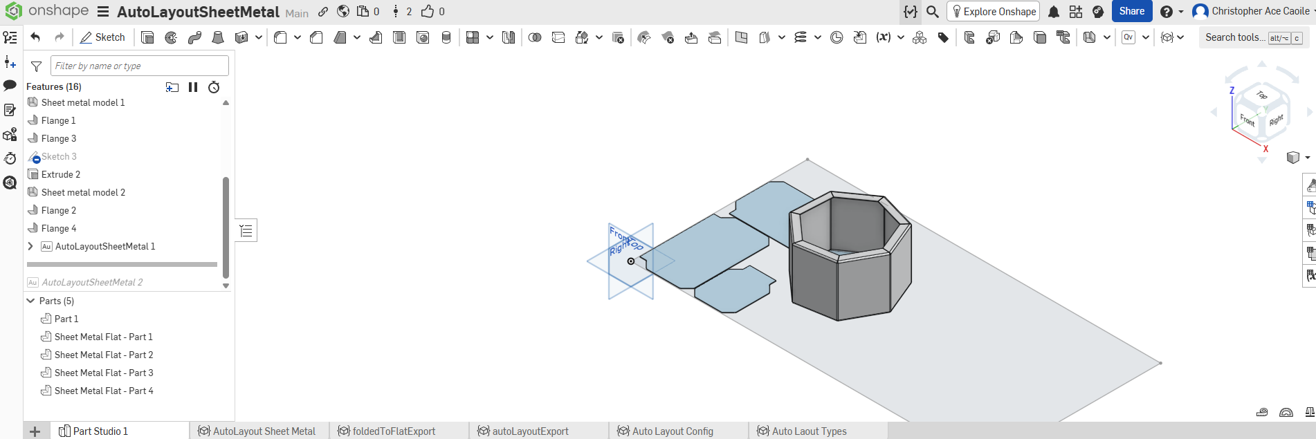 2
2 -
This is indeed awesome! Thanks @lemon1324 and also @eca_elioac refactor very handy.
I think the real strength of this feature is arranging pieces of irregular shapes in a square surface.
But what about multiple copies of the same shape?
As far as I understood it, there's no option to clock a set of instances or offset them, right?
That would be in order to make the packing more efficient (right picture is made manually with transforms)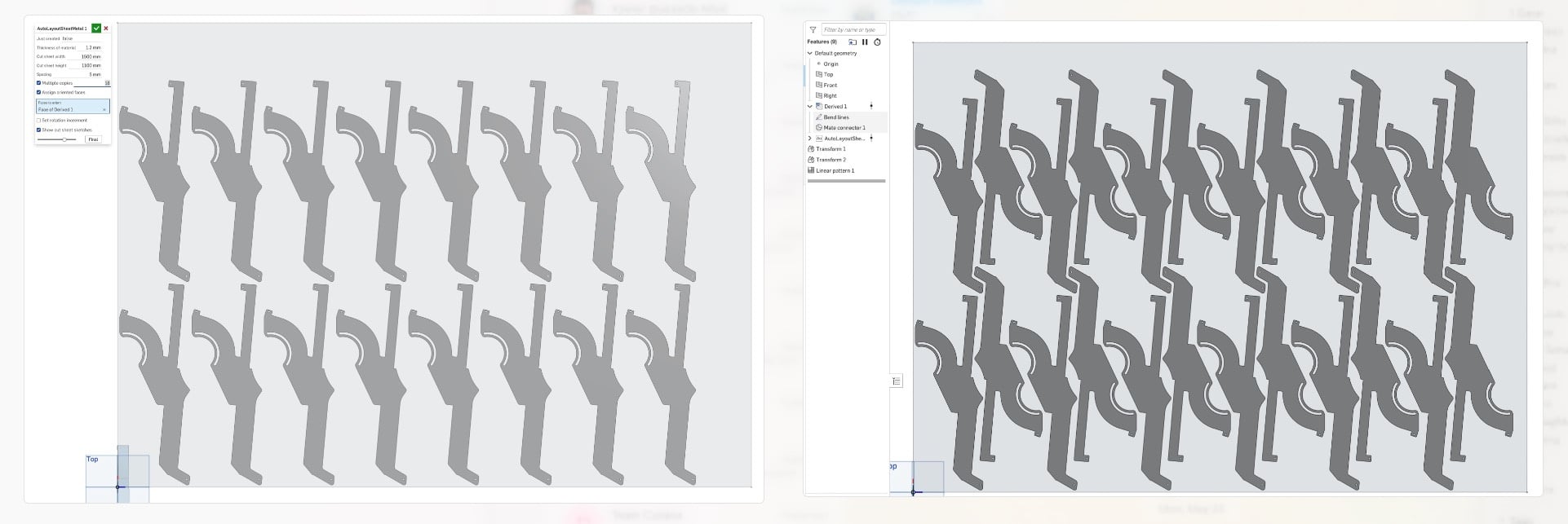
Am I right that the FS doesn't can't produce a more efficient layout than the left picture?
Iterating once more, I brought it to almost double: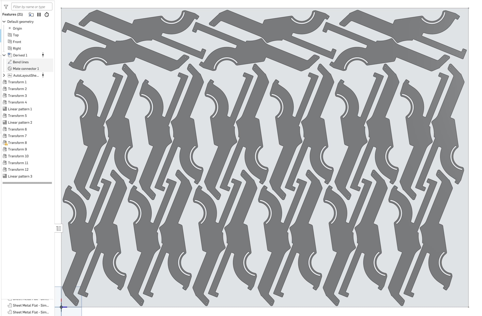
Since I have insufficient FS knowledge to build this myself, I'm throwing the idea to the community of how I would replicate this algorithm in a custom feature:
A user would procedurally "stack" geometric operations on the fly within a single feature dialog box using an expandable array panel.- Sequence Parameters: (An expandable array panel where you can click "+ Add Step")
- Each step has
- Selection of instances (Parts and Sketches)
- Operation Type:
[ Dropdown: Move XY / Rotate Z / Linear Pattern ] - + Corresponding Parameters
- Each step has
This puts the entire algorithm inside one clean control panel feature.
If no one picks up the glove, I promise this will be one of the first I'll try when I learn how to (vibe :-)code FS
Cheers1 - Sequence Parameters: (An expandable array panel where you can click "+ Add Step")
-
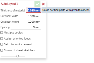
@lemon1324 does this feature not work with lofted parts? (Used the "thin" feature in loft to make my parts. So, all the parts have the same thickness. Also, I was trying it on Curved loft "thin" surfaces. Is that why I wasn't able to get Auto Layout to work?
 0
0 -
@Devam_Purohit the tool is a FeatureScript approximation of a true layout tool. Since FeatureScript should run reasonably quickly and deterministically, I don't flatten anything, it only works on already-flat parts. If you happen to make a truly flat-and-parallel lofted part it should work, but for anything curved that's out of scope for this particular tool. I'd suggest using a flattening tool of your choice and then an external nesting tool if you're trying to get more optimal results.
Arul Suresh
PhD, Mechanical Engineering, Stanford University1