Welcome to the Onshape forum! Ask questions and join in the discussions about everything Onshape.
First time visiting? Here are some places to start:- Looking for a certain topic? Check out the categories filter or use Search (upper right).
- Need support? Ask a question to our Community Support category.
- Please submit support tickets for bugs but you can request improvements in the Product Feedback category.
- Be respectful, on topic and if you see a problem, Flag it.
If you would like to contact our Community Manager personally, feel free to send a private message or an email.
Best Of
Re: Entering Variable name on Sketch Dimension changes view
Best option is to type use an equal sign (like Excel), that way you don't need to delete anything. It would be nicer if it accepted "#" directly though…

Re: Editing in Context Question
Thank you David,
I had fogotten about being able to use derived for sketches. That worked great, and kept the sketch positioned just like I needed it.
I appreciate the help.

Re: Entering Variable name on Sketch Dimension changes view
You're not crazy. You need to type a number to activate the dimension field. Then you can delete the number and type #. Otherwise, you will activate the Shift+3 keyboard shortcut for Left. I don't know of a workaround.

Re: How to extrude imported parts with a featurescript
Here is a simple example of how to instantiate a pre imported part as well as letting the user choose like a derive:
https://cad.onshape.com/documents/bf218127a4290c050e205e75/w/42342e313f737ad5d1388f67/e/26b5c545d60a0412c45a7108…
And here is a more complex example showing how to access configurations and drive them with maps:
https://forum.onshape.com/discussion/26452/product-catalog-new-custom-feature…
.

Driven variable in Variable Studio

Re: How to design using the center of gravity/center of mass
Hi,
use this Custom Feature.
https://cad.onshape.com/documents/f5fee8f3ea87a78348241032/v/1a65269f7bee15e5b354bd56/e/bf1edf08ce234ce26d01d5ad

Re: Onshape but offline, called OFFSHAPE
This is a great idea, there quite a few users who also would like some sort of offline backup.
While I support and enjoy 99.9% of Onshape which is unparalleled by any other cad system imo, there are two potential risks that come with it.
- No offline 1st party backup cad system
So if you need true backups, you have to find 3rd party cad and use exported parts which does not save the feature trees or assembly mates etc… - PTC / Onshape or Amazon can ban your account / region (Someone correct me if this is incorrect)
This means that your CAD is directly related to PTC and Amazon's political wars with the world. If you or your country has done something that they don't "like", then your account could be banned, risking all of your data when you may not even have been involved in their political battle.
.
Re: Surfacing Nightmare- Can't get these corners
EDIT: this advice is more general, as many of the techniques I used at Honda were done with custom software, and don't work in Onshape. So different approaches may be needed.
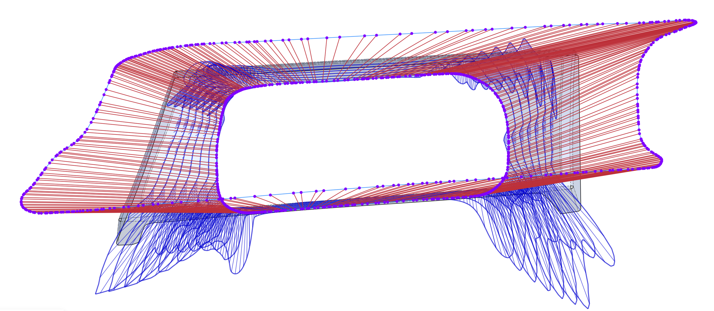
one of the other most important things to keep in mind (besides breaking down shapes like that into slabs and corners) is that, ideally, the surfaces should either be made out of as few boundary curves as possible in order to have good surface quality and highlights/reflections (as can be seen with zebra analysis).
- one edge would just be a straight extrude
- two edges would be a blended corner, but now that you have two curves on opposite ends of the surface, you need to try and ensure that they are related to each other, as in they have the same DNA. if the two curves have very different shapes and construction, it could cause issues in the surface shape and quality.
- three curves would be a bi-rail surface, but unfortunately i don't think Onshape has these.
- four curves is available, but again, you should try to make sure that the opposite curves are related as closely as possible.
the corners of your "i solved it" tab are made from curves that are very different. rounded in the back, and sharp in the front (with extended straits at each end) It may be easier if you try to blend the two slabs and just let that blended surface cut through the front and back to create natural corners. if you want, you can make tapered lines to blend from, so it gets tighter in the front corner. but just let the blend cut through the front face.

Re: Surfacing Nightmare- Can't get these corners
Right now this is view only, so I can only investigate so much…
That said, I would avoid loft, and avoid lofting so much in one feature. I would recommend constructing the cleanest, most simple curves you can for each of the sides of that shape, and then build the corners from that. Right now you're getting a surface which is way too dense and not great quality.
While Onshape doesn't have all the same tools, this series of tutorials on surfacing with Alias might help you with how to break things up and use better techniques:
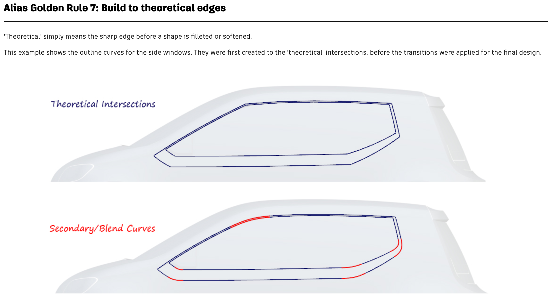
One of the most important things in this case, would be to "build to theoretical edges"
These videos from Onshape's @GregBrown goes into some of the newer curve features and techniques for dealing with scan data:
 S1mon
S1mon
Re: SurfaceText Problem with Cut Out function
Hi, I had the same issue with Surface Text as Vincent _bombonel:
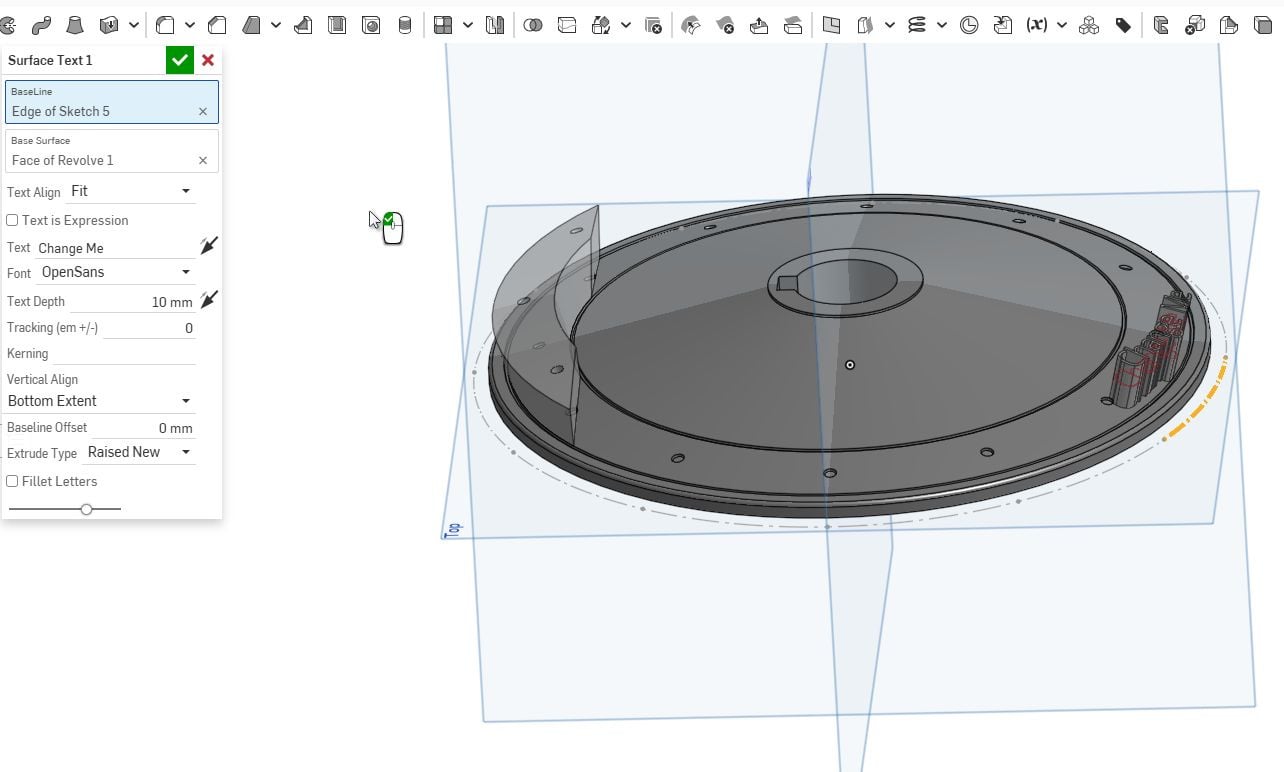
I lost many hours trying to fix it. Finally I was lucky to find this topic and was able to solve the problem with the Text feature from jnewth.
Many thanks 🤗