Welcome to the Onshape forum! Ask questions and join in the discussions about everything Onshape.
First time visiting? Here are some places to start:- Looking for a certain topic? Check out the categories filter or use Search (upper right).
- Need support? Ask a question to our Community Support category.
- Please submit support tickets for bugs but you can request improvements in the Product Feedback category.
- Be respectful, on topic and if you see a problem, Flag it.
If you would like to contact our Community Manager personally, feel free to send a private message or an email.
Best Of
Assembly Drawing - Cannot create "zero" (0.00) dimension between parts aligned on the same plane.
I have an assembly drawing of a stack of components. Some of the components need to align on the same plane. On a cross-section, I would like to show that the edges of the two parts can be aligned with some tolerance (i.e. 0.00+/-0.50mm). For the life of me, I cannot create such dimension. I have tried line-to-point, point-to-point, line-to-line and min/max dimension options - to no avail. The ONLY way to create such dimension is to create a small offset in the assembly, then create a dimension on the drawing and then having to go back to the assembly to remove the offset. Voila, the drawing updates and shows 0.00! However, I would like to avoid doing that every time something changes on my assembly.

Re: Best performance method to make or use parts with hundreds of grid holes
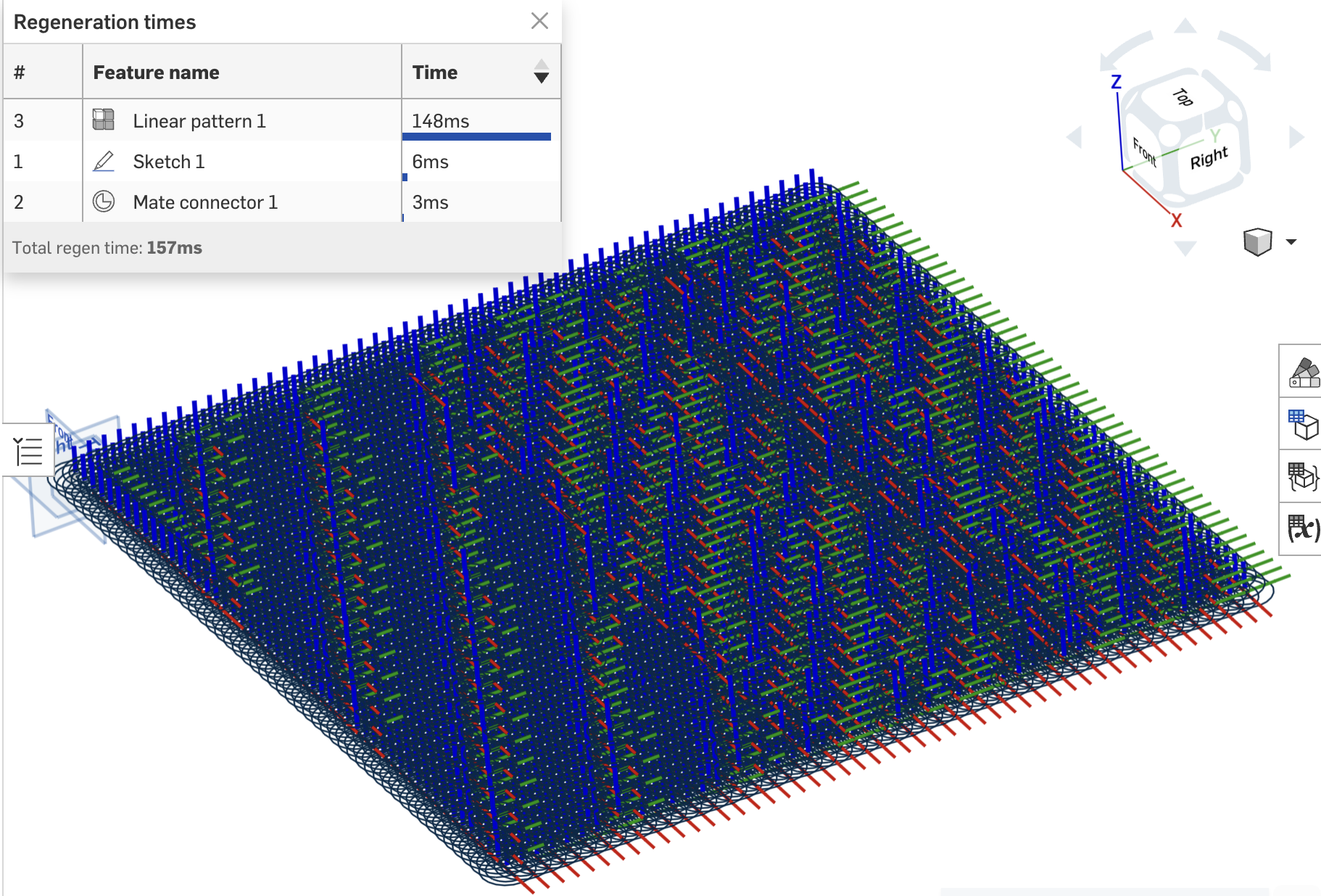
i think @GregBrown might have some recommendations here. He's been experimenting with similar problems. In terms of holes, you dont actually need the geometry, do you? You just need the position (and we assume the diameters are all the same, standard, and all holes are through). Could you pattern just a mate connector at every hole location? I suspect this would be a lot lighter. I just did the max pattern count (2500 instances, 50x50) and regen time from just patterning mcs is ~150ms.
 jnewth
Transfer user preferences and custom feature lists from one account to another?
This would be useful for teams with that one power user who has their prefs and custom feature list dialed in to help their team mates get set up too, or, in my case, to get the same settings across multiple accounts. I know Enterprise can to their own custom feature toolbar, but that's not what I'm talking about here.

"Use"ing a "Derived" part breaks when Derived location changes
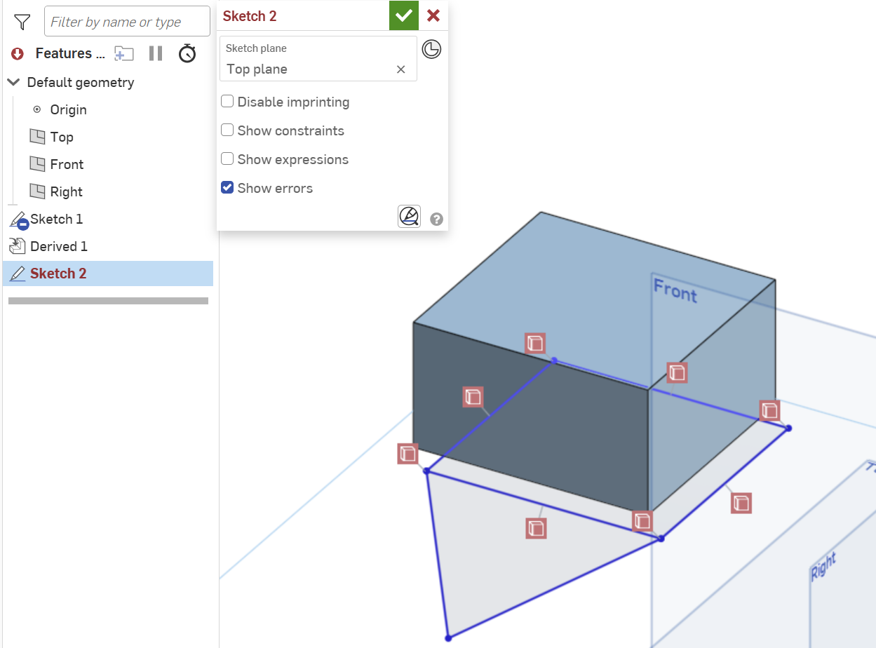
I get some weird behavior when changing the location of a Derived part that is Use'd in a sketch. All my Use constraints are broken. Steps to repro: (see Part Studio 1 and Part Studio 2 for an example)
- Define Part 1 in some Part Studio
- Derive Part 1 into some other Part Studio (e.g., Part Studio 2) and set the location to be some vertex
- Create a sketch in Part Studio 2 and Use a face of the derived Part 1
- Add some lines in the sketch that connect to vertices of the Use'd Part 1 and complete the sketch.
- Edit the Derived feature and change the Location to be the Origin (likely any other location fails too) and complete the feature edit
- Notice that the sketch containing the Derived Part 1 is now full of unresolved references for all the Use'd elements of Part 1.
What have I done wrong? Is there a way to update all the references? Is this a bug? Seems like a major limitation of Derive/Use if the Derive feature Location can never be changed once added.
Re: Custom Feature: OnlyTabs - A premium sheet metal tab and slot feature
Oh I suppose this isn't clear from the demo docs I chose, but your tabs can make slots in the middle of sheets as well. Most of my projects and use case will be edge alignment but you can use this for parts alignment in the middle of a sheet too.
And on a similar note the slot body doesn't have to be sheet metal - it can be frames or other solid parts. You'll just find that the slots won't go all the way through your slot body unless the tabs go all the way through the slot body.
This is 50% because this is how you should be doing your tabs on frames for manufacturing and structural reasons anyway, but 90% because I'm cheating with the slotting logic being handled by the sheet metal engine handler to ignore the need to check for wall thickness for the slotting operations in general runtime.
V19 - Updated the script because I goofed the implementation of the RNG. It's actually random now.

Re: Issues with loft end conditions - Model Mania 2005 Part
yes, if you turn on the Connections option you'll see something like this:
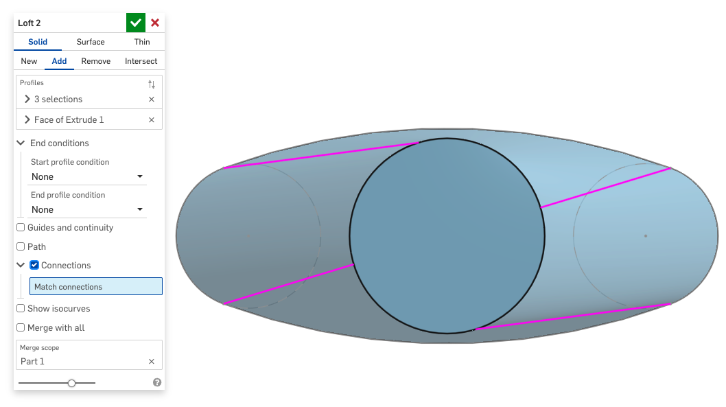
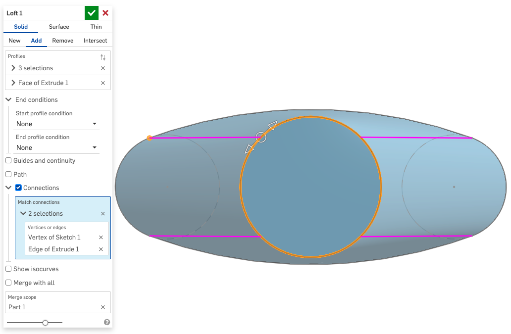
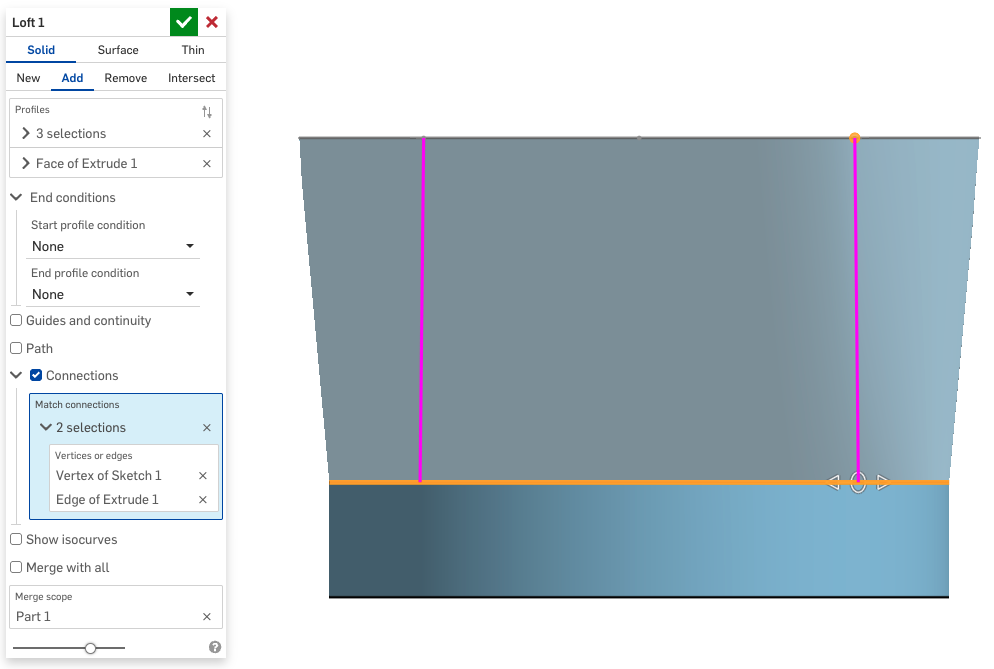
In this case all you have to do is create one "connection" from the arc to the circle and drag the manipulator around until it's right:

Re: Best performance method to make or use parts with hundreds of grid holes
I worked on a customer project that had a similar issue. Metal extrusions with holes every inch.
What we did was create a configuration checkbox for the parts to turn the holes on and off.
If you aren't mating to the holes, then you can turn them off when they aren't needed. Obviously this workflow doesn't work for every case, but it made a huge difference for that specific workflow. Not making the holes is faster than any method of making them.

Re: How to make a slanted hole specifically 72 degree angle
No need to create a plane. Just create a Mate connector, using the existing face as a reference and an offset angle. Then forget about sketching your hole in this new plane and extrude it, just use the hole feature instead. ;0)

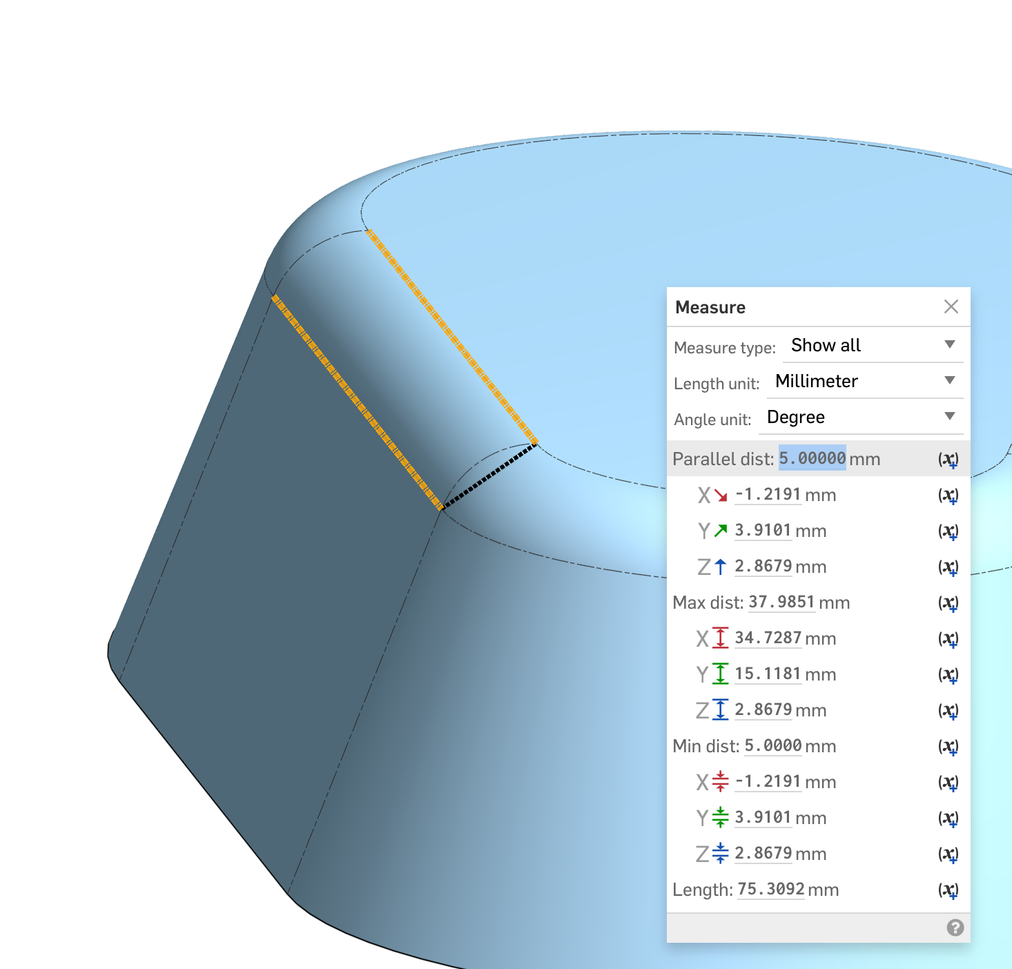
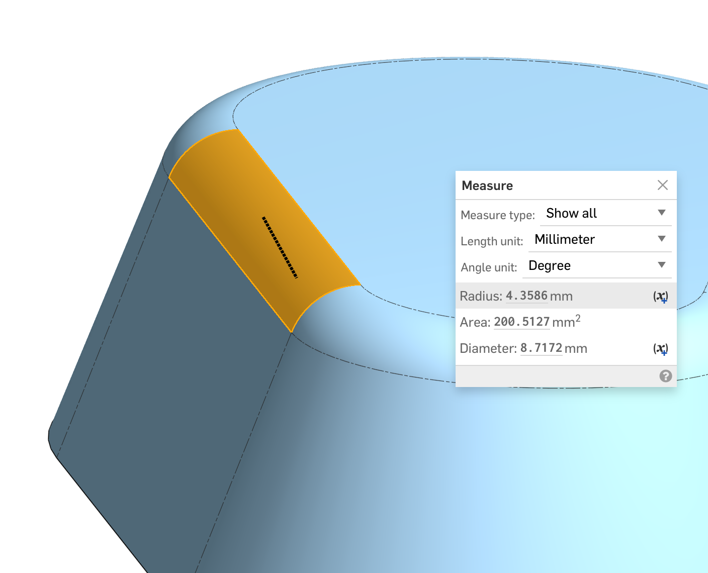
Re: Fillet - Not working as it used to?
The top fillet in this part is set to Width and 5mm. The width is the chordal distance and drives the size. The radius value is a resultant.
 S1mon
S1mon