Welcome to the Onshape forum! Ask questions and join in the discussions about everything Onshape.
First time visiting? Here are some places to start:- Looking for a certain topic? Check out the categories filter or use Search (upper right).
- Need support? Ask a question to our Community Support category.
- Please submit support tickets for bugs but you can request improvements in the Product Feedback category.
- Be respectful, on topic and if you see a problem, Flag it.
If you would like to contact our Community Manager personally, feel free to send a private message or an email.
Best Of
Re: Making two different color ways of my product in one document, is this smart?
Duplication is generally a bad idea!
Use configurations instead! You might want to use something like the excellent part color FS to set the colors as it's easier to work with than the built-in "configured properties" workflow.
https://cad.onshape.com/documents/d997b0ffc30f659113b10c00/v/a9e4f209775174dbb9f2b5fa/e/b6db0c9545b9a2df1d7ea546

Re: Detail look correct, but 9 features failed to regenerate
To clarify: because the edges are tangent-continuous, chamfering one edge on the top and one on the bottom, with tangent propagation on, will create what looks like the right chamfer.
There are many redundant features, both for holes and chamfers. Might I recommend our learning center? https://learn.onshape.com/
 _anton
Re: how can I have a single set of configs across parts studio, assembly, and drawings
@david_lang457 I think I get what you want to happen. Correct me if I am wrong, but my understanding is that you want to be able to change the config of a part or assembly and then go into the drawing and have the drawing just automatically be referencing the same config you were just viewing in the part/assembly. Or your looking to some way change one set of inputs and have model and drawing change at the same time. It does not work that way and for good reason. The system as a whole is very stable because it does not work that way. Drawing's reference a certain configuration of an item and will not reference any other one unless explicitly changed. When I started digging into configs and using configured items in drawings, I too was slightly baffled at first and had to do a double take at finding how best to set myself up. I think it is best to view this problem by always starting at the top ie. drawings. I usually do not ever use the configs setup in an assembly or part directly but usually start at the drawing and change the drawing to reference the config I want. When the drawing is finished processing the change, one can start digging down. You can double click a drawing view and then switch to the item represented in the view by clicking the blue item link. When the model opens up, onshape will have set it to the same config referenced in the drawing. So generally, you can just duplicate a drawing, change it to reference a different config and then use the drawing as your master starting point to reference down into the correct config of the models. You do not actually need to change configs of anything but the drawing because the drawing will changed the child items configs for you as you start referencing down into them.
If you were to setup your drawings into a different document than the ones where the models are, users do not need edit rights to the models, just the drawings and then can duplicate or they can copy and paste them out into what ever document they may want to put them in. All the while, they are still able to open up the model to be viewed automatically having the config set correctly by the system.

Re: new Featurescript: Statics Solver
Im not familiar with that method. Mine uses 3d force vectors and their moments to calculate the unknown forces and directions.

Re: new Featurescript: Statics Solver
If I can make this, they can easily incorporate it.
Lmk if you find some of the many deficiencies in my FS.
Re: How can I add text in a Sketch that contains a Caron (e.g., Unicode U+030C (ǒ))?
@GregBrown : OMG, thanks! I had randomly tried a several fonts that happened not to be any of those you listed. I gave up too soon. doh! I'm switching to Arimo. Thanks again!

Re: Gear Lab - Cylindrical, Bevel, Face Gears
I affirm the issue Lazar brought up r.e. the bevel angle. I was able to resolve my issue by going to this calculator:
Importing the number of teeth I want and my desired shaft angle, and then picking any face width. Adjusting the face width didn't seem to affect things. Then, I took the bevel angle output from that calculator and input it into OnShape. Onshape is still reporting shaft angles about five thousandths of a degree off from perfectly level, but I think that the manufacturing processes I'm using are not up to producing this level of precision anyway, so this is good enough for me.
The ideal would be if the featurescript could be updated to automatically calculate the bevel angle. The trigonometry for it does not look that difficult:

The known terms are E, z1_m, and z2_m. We just have to solve for the two smaller angles. I have forgotten the trigonometry that can be used to do this, but OnShape knows how to do it for me!
https://cad.onshape.com/documents/7cdf7f6e4d2f3a54505e4354/w/ba750b40c81df34fce85dc6c/e/6bd6eab9eb8b7e7a3625c895?renderMode=0&uiState=6716ebe4a1a9462e4e2bccae
If you look at the sketch I made, I tried to replicate the diagram shown in the image.

The two driven dimensions are the bevel angles of each gear. You can see that the sketch matches the gears pretty much exactly if you roll to the end of the document. If I input the angle between the vertical line and the the right side of the triangle as the bevel angle of the first gear, then I get a perfect 90 degree angle on the shafts. I don't know how to create driven angles in OnShape, and I can't figure out how to edit gearlab, so I guess doing this by hand is necessary for now. But if someone could update this FS to do this automatically that would be cool.
Re: Is there a FONT for Text that is automatically ok for stencils
Allerta Stencil will do it.


Re: Configurable Variable in Part Name
I have an assembly with several... several (>100) configuration combinations. I was hoping to build a smart string for the part number based on the configuration parameters but I am struggling to figure something out. As of right now, for my assembly, the only way I know how to populate all of the part numbers is to hard code them for each configuration. I need to do this because when exporting these assemblies to a PLM (e.g. Duro), I want the PLM to catch that the part already exists and not have someone create a new part number for an existing assembly.
To me, this is the single most important reason of being able to build a smart string in the part number field of an assembly.
cc: @alan_baljeu

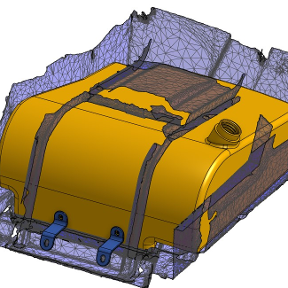
Re: Methodology for building a part which interfaces to a point cloud?
Been doing this sort of thing for awhile now. but looks like you may have figured it out. the basics for anyone searching down the road are create planes and curves based on the mesh vertexes and go to town.
 MDesign