Welcome to the Onshape forum! Ask questions and join in the discussions about everything Onshape.
First time visiting? Here are some places to start:- Looking for a certain topic? Check out the categories filter or use Search (upper right).
- Need support? Ask a question to our Community Support category.
- Please submit support tickets for bugs but you can request improvements in the Product Feedback category.
- Be respectful, on topic and if you see a problem, Flag it.
If you would like to contact our Community Manager personally, feel free to send a private message or an email.
Best Of
Re: Unit conversion
Re: derived feature in part studio, hiding derived sketches
Your document hasn't been updated lately.
Trash the document and then recover from trash. It will put up a dialog about updating next time you open. Once updated it will behave as S1mon says.
Re: Extruding a QR code
Never mind. I was not using all the options correction. Thanks! This is cool.
Re: Best Way to Mirror Parts In Place (Without Creating New Parts)
I ran into this exact need and developed Lefty Flip as a custom feature to do exactly what you're asking. It does work as a negative bounds scale transform under the hood and maintains all part and face identities as you're expecting. There's a little bit of sheet metal magic in there too.
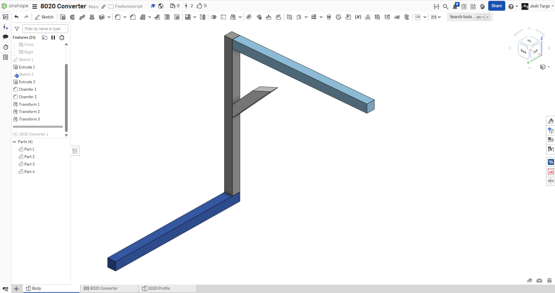
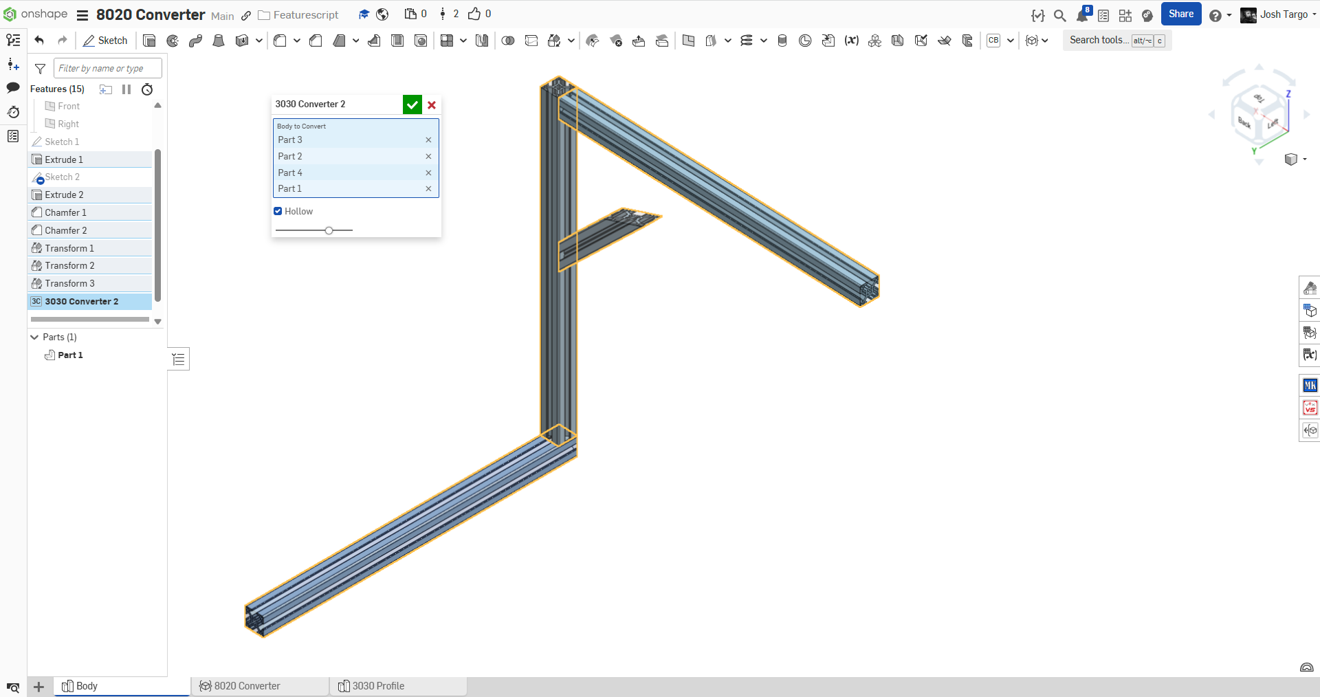
New Custom Feature: 8020 "3030" Profile Converter
A custom feature to bulk convert 30x30mm prismatic bodies (works with with mitered ends) into 8020 "3030" profile aluminum extrusion.
future enhancements will obviously be the ability to convert to other profiles, possibly automatically.
can anyone tell me where the official Onshape 8020 library document is?
Re: Custom Post Processors
I'm currently on the free plan, so no access to support tickets from what I can see. I'm considering an upgrade to the Pro plan if the machines I have are supported - how can I suggests machines to the CAM Studio folks?
Re: Custom Post Processors
We are waiting for this feature too. We have a Mecanumeric CNC machine, so we have to export our Onshape CAD designs and switch to Fusion 360 every time we want to produce a part since it is not in the default list of supported machines… I opened a ticket though (ticket: #387081), I hope my request can be treated promptly. Cheers
Re: Custom Post Processors
Please report back here on the help you receive about this. Perhaps Onshape CAM Studio is supported better than the traffic on the forum would suggest.
Re: New Custom Feature: 8020 "3030" Profile Converter
I agree that it's frustrating to not be able to configure each member's 9-point manipulator selection. I've just started using it for real recently myself, and found that quite problematic. We can individually flip butt joints, but not individually pick from the 9 points.
However, it's not that hard to just create multiple frame features. That seems much easier for now and better supported.
 S1mon
S1mon


