Welcome to the Onshape forum! Ask questions and join in the discussions about everything Onshape.

First time visiting? Here are some places to start:
  1. Looking for a certain topic? Check out the categories filter or use Search (upper right).
  2. Need support? Ask a question to our Community Support category.
  3. Please submit support tickets for bugs but you can request improvements in the Product Feedback category.
  4. Be respectful, on topic and if you see a problem, Flag it.

If you would like to contact our Community Manager personally, feel free to send a private message or an email.

Polyhedron constructions? calling for pros help

otaolafrotaolafr Member Posts: 113 EDU
edited January 2019 in Using Onshape
hello everybody,
i am looking for help from the pros from onshape.
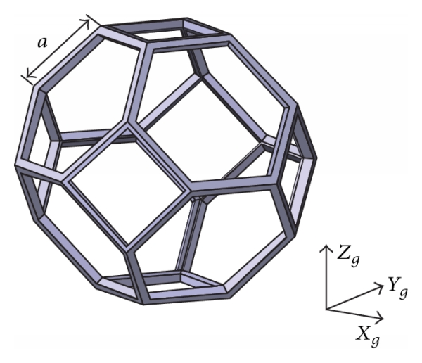
i am looking to make different "simple" geometries, void polyhedrons, like the ones from this photos controlling sizes of the faces and also the sizes of the "edges"
 and after that make a stack of them like the second image (in the image they are the polyhedrons are "full" but i would like to do it with "empty" ones like the one from the first image)
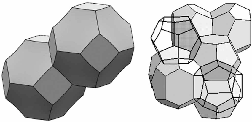
i want to do with different types of geometries (like cubes, diamont, etc....) 

i can see how to create them in onshape, stack them (almost sure...) but i think it would be really machine consuming as what i want to do is like a "foam" or "sponge" of them.

i would like to know how you would do it and the fastest or easiest (and cheapest in machine demanding)

i thoung about doing from creating a lot of different planes form the first polygon and from that, create the other ones, and use another perpendicular plane for each line and use the sweep option for creating the "edges".  but i can see how it would use so many features that i am not convinced at all that is the way to go.
also i though about doing surfaces, then mirroring them and use the beam FS in their borders but also i dont see it as a good way to go.

also i saw about the FS 3Dpointgen, (https://forum.onshape.com/discussion/comment/34682#Comment_34682) but not sure if it would be the best way to go either....


any good advice would be greatly appreciated as i am a little bit lost, for someone that learn CAD alone. 

the final result would be something like this:
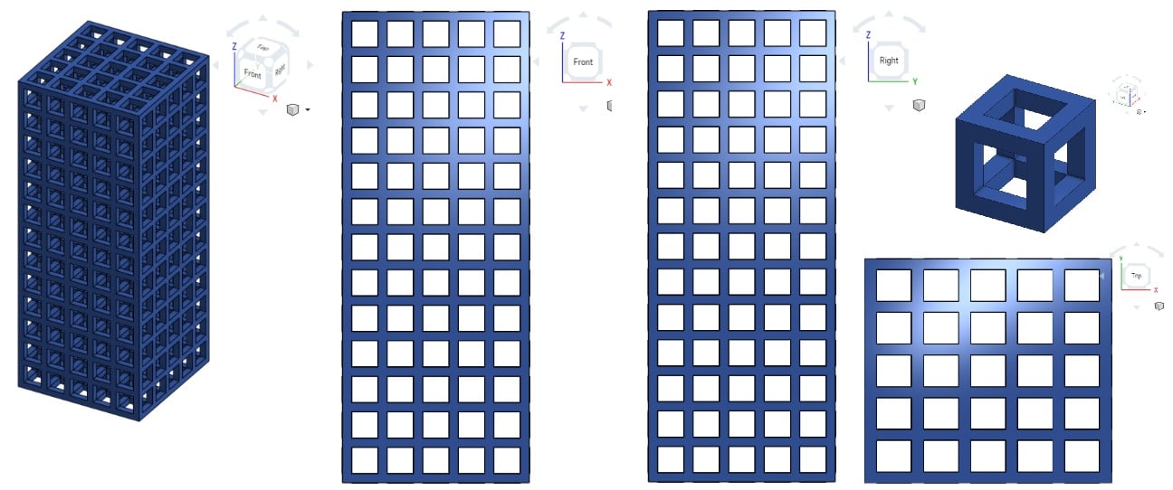
with having different cell types to make the stacks. 
Tagged:

Comments

  • konstantin_shiriazdanovkonstantin_shiriazdanov Member Posts: 1,221 ✭✭✭✭✭
    There is a Polyhedron custom feature by John Sorrels among public documents for this kind of regular polyhedrons, my feature is for making convex solids from a set of vertices, that feature is for generating regular polyhedrons from scratch
  • owen_sparksowen_sparks Member, Developers Posts: 2,660 PRO
    Like this:-


    O.S.
    Business Systems and Configuration Controller
    HWM-Water Ltd
  • otaolafrotaolafr Member Posts: 113 EDU
    edited January 2019
    There is a Polyhedron custom feature by John Sorrels among public documents for this kind of regular polyhedrons, my feature is for making convex solids from a set of vertices, that feature is for generating regular polyhedrons from scratch


    @owen_sparks , thanks to both of you
    @jon_sorrells for the FS
    yes but still have several questions,
    • fist: using the FS, uses fewer features but, is also better for the computer consumption? 
    • second: as the fist polyhedron i post it, a (tetrakaidecahedron, more specifically a Truncated octahedron) it has faces with different polygons ( in that case 8 regular hexagonal and 6 square) in that cases the best would be to use your FS and creating the points or doing with different planes, sketches and features etc... ?
    • third: how to "empty" in an easy way? or i would use the body created and then features like sweep to create the "skeleton" of it?

    to arrive to do it "skeleton" i needed to create two different polyhedrons of different sizes and do one extrusion for each face of the small polyhedron and then extract that one from the bigger one so, two polyhedron FS + 12 extrusions (for each surface) + a subtractive boolean. 

    (not at all a fancy way ahahahahahaha) :D:D:D:D:D
    • fourth:to stack them, you would go with 3 different linear patterns? or something else? 

    i am asking all this because when i created the one from the cubes ( the third image) onshape takes some time to charge the model, and i have done it using, beam FS, and linear patterns, and it would be the "simplest" of the geometries. 
  • jon_sorrellsjon_sorrells Onshape Employees Posts: 51
    • second: as the fist polyhedron i post it, a (tetrakaidecahedron, more specifically a Truncated octahedron) it has faces with different polygons ( in that case 8 regular hexagonal and 6 square) in that cases the best would be to use your FS and creating the points or doing with different planes, sketches and features etc... ?
    My custom feature can do truncated polyhedrons too.

  • konstantin_shiriazdanovkonstantin_shiriazdanov Member Posts: 1,221 ✭✭✭✭✭
    I'm not near pc, but i beleve substracting extruded faces of internal polyhedron from external one should work better then you expect, just try to box-select all the faces of internal polyhedron in one extrude feature
  • otaolafrotaolafr Member Posts: 113 EDU
    I'm not near pc, but i beleve substracting extruded faces of internal polyhedron from external one should work better then you expect, just try to box-select all the faces of internal polyhedron in one extrude feature
    I didn't understand you, sorry. i also tried with thicker that would be really handy for this situation (thicker the faces of the internal one) but with one face works great, but when i choose another one that shares an edge the thicker feature "sticks" them together. for the moment what i found better than the 12 extrusions (at least a progress) is to use three thicker features for the faces that don't share edges, and it outperforms 30% the extrusion approach. :smile:

    and for the stacking i went with an assembly of four of them, stacked by mate connectors -> create a part studio in context -> then copy in place and union boolean each of them
  • kevin_o_toole_1kevin_o_toole_1 Onshape Employees, Developers, HDM Posts: 565
    One question is what exactly you want the boundaries to look like when two polyhedrons are placed side by side. The edges on your image have clear flat sides around each face, but in the final wire, each edge will be touching more than two faces, so it's not clear to me what exact geometry you'd want there.

    If the edges can all have the same profile, I think the easiest option is to use the Beams feature. For the lines, you can either select the edges of a single solid polyhedron, or select all edges of many patterned solid polyhedrons (for the latter, it will be helpful to select View cube menu > Hidden edges visible). For the beam profile, you can select a "custom" profile pointing to a Part Studio with a simple sketch. Pointing to a sketch of a small circle, for instance, would make all of the profiles cylinders.

    For large lattices, the beams feature will end up being very slow to regenerate, but in return it could save a lot of time modeling.

  • MBartlett21MBartlett21 Member, OS Professional, Developers Posts: 2,050 ✭✭✭✭✭
    edited January 2019
    There is a Polyhedron custom feature by John Sorrels among public documents for this kind of regular polyhedrons, my feature is for making convex solids from a set of vertices, that feature is for generating regular polyhedrons from scratch


    @owen_sparks , thanks to both of you
    @jon_sorrells for the FS
    yes but still have several questions,
    • fist: using the FS, uses fewer features but, is also better for the computer consumption? 
    • second: as the fist polyhedron i post it, a (tetrakaidecahedron, more specifically a Truncated octahedron) it has faces with different polygons ( in that case 8 regular hexagonal and 6 square) in that cases the best would be to use your FS and creating the points or doing with different planes, sketches and features etc... ?
    • third: how to "empty" in an easy way? or i would use the body created and then features like sweep to create the "skeleton" of it?

    to arrive to do it "skeleton" i needed to create two different polyhedrons of different sizes and do one extrusion for each face of the small polyhedron and then extract that one from the bigger one so, two polyhedron FS + 12 extrusions (for each surface) + a subtractive boolean. 

    (not at all a fancy way ahahahahahaha) :D:D:D:D:D
    • fourth:to stack them, you would go with 3 different linear patterns? or something else? 

    i am asking all this because when i created the one from the cubes ( the third image) onshape takes some time to charge the model, and i have done it using, beam FS, and linear patterns, and it would be the "simplest" of the geometries. 
    You should be able to use shell and select all the faces
    EDIT: It doesn't work :(
    mb - draftsman - also FS author: View FeatureScripts
    IR for AS/NZS 1100
  • otaolafrotaolafr Member Posts: 113 EDU
    One question is what exactly you want the boundaries to look like when two polyhedrons are placed side by side. The edges on your image have clear flat sides around each face, but in the final wire, each edge will be touching more than two faces, so it's not clear to me what exact geometry you'd want there.

    If the edges can all have the same profile, I think the easiest option is to use the Beams feature. For the lines, you can either select the edges of a single solid polyhedron, or select all edges of many patterned solid polyhedrons (for the latter, it will be helpful to select View cube menu > Hidden edges visible). For the beam profile, you can select a "custom" profile pointing to a Part Studio with a simple sketch. Pointing to a sketch of a small circle, for instance, would make all of the profiles cylinders.

    For large lattices, the beams feature will end up being very slow to regenerate, but in return it could save a lot of time modeling.

    mmm dont think beam would be a good idea, (well i thought it was...) from my first post where i made the cube one, the beam FS make it very very slow.... thats why i was asking, but yeah, the process that you described was exactly what i have done :)
    thankyou !
  • tim_hess427tim_hess427 Member Posts: 648 ✭✭✭✭
    @Otaola_Franco, You might want to look at a dedicated lattice design tool like https://www.ntopology.com/.  Their process designs the lattice with line segments, then thickens them as a last step. I think they used to have a free version, but I'm not seeing it anymore, which is a bummer.

    Also, if you haven't seen this before, there's a webinar with a bunch of great tips for optimizing your models/documents for better modeling and rendering performance. One thing that might help, is that if you're creating patterns, use face patterns where possible instead of feature patterns. The webinar and a summary can be found here:


Sign In or Register to comment.