Welcome to the Onshape forum! Ask questions and join in the discussions about everything Onshape.
First time visiting? Here are some places to start:- Looking for a certain topic? Check out the categories filter or use Search (upper right).
- Need support? Ask a question to our Community Support category.
- Please submit support tickets for bugs but you can request improvements in the Product Feedback category.
- Be respectful, on topic and if you see a problem, Flag it.
If you would like to contact our Community Manager personally, feel free to send a private message or an email.
Best way to create angled holes for splayed legs
 Skippy
Member Posts: 50 ✭✭
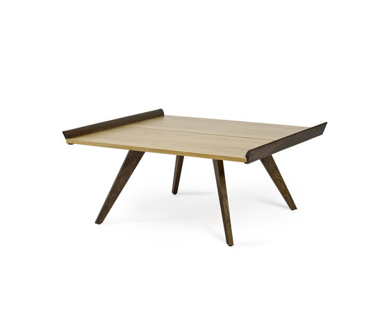
Im trying to add angled holes to the base of a rectangular project that will hold 8mm rod as legs. There will be 4 legs, one at each corner and each angled out to the corners at about 20 degrees. I found a picture of a coffee table with roughly what I mean.
The only way I've found to do this is to use move face on a cylinder twice in two axis to angle it and then use that to boolean out the holes (I can also copy the cylinder to use as the leg itself).
Im wondering if theres a better way to go about this? Im extremely new to CAD so if this is a very easy question I apologise.

0
Best Answers
-
 dustin_hecocks
Member Posts: 10 ✭
Hi @nick_grant . The creation on planes in OS has a ways to go. As such, the part you are trying to create can become a little tricky. I have attached a quick mock up of a table, angled legs, and angled holes in the table top to the legs. I apologize for how sloppy it is; I just drew it quick without dimensioning a thing.
For things like this I have always used planes. However, I found creating planes for this task to be somewhat difficult. To the point where I created the holes by drawing the circles on the face of the table, and swept the cut using the table leg sketch as the sweep path. It works, not easily and clearly, but it works. And from there I'd mirror til its done. Does that help at all?
Angled legs1 -
 jakeramsley
Member, Moderator, Onshape Employees, Developers, csevp Posts: 669
  Depending on the shapes of the entering/exiting cross-sections, I would consider drawing those on the top and bottom faces of the table then lofting between them with a remove.Jake RamsleyDirector of Quality Engineering & Release Manager onshape.com5
Answers
For things like this I have always used planes. However, I found creating planes for this task to be somewhat difficult. To the point where I created the holes by drawing the circles on the face of the table, and swept the cut using the table leg sketch as the sweep path. It works, not easily and clearly, but it works. And from there I'd mirror til its done. Does that help at all?
Angled legs
Indaer -- Aircraft Lifecycle Solutions
refer the model
https://cad.onshape.com/documents/8d23d2ae65a64bbfa40412b0/w/ed655ae059e44defab444e0a/e/d7ce793467ff44b097165fdf
You will need to un-hide the surface to see how this was done.
I used sweep to model the legs along the inclined edges of the resulting surface body.
For the cylindrical rod legs, I made a plane for the sketch, using the "Curve-Point" specifiers.
The rationale for using sweep, instead of extrude, was simply that (at present) there is no "extrude up to vertex" end condition, so a sweep is the best way to simply capture the desired intent.
In the other, (which I did simply to show why the extra plane was necessary) the sketch was on the "Top" plane, resulting in an elliptical leg
Thanks