Welcome to the Onshape forum! Ask questions and join in the discussions about everything Onshape.
First time visiting? Here are some places to start:- Looking for a certain topic? Check out the categories filter or use Search (upper right).
- Need support? Ask a question to our Community Support category.
- Please submit support tickets for bugs but you can request improvements in the Product Feedback category.
- Be respectful, on topic and if you see a problem, Flag it.
If you would like to contact our Community Manager personally, feel free to send a private message or an email.
Multipart Part Studio
 anthony_2
Member Posts: 1 ✭
anthony_2
Member Posts: 1 ✭
I'm pretty new to using Onshape, so pardon me if this is pretty well traversed ground. I'm trying to model the mount for a cylindrical object that consists of two saddles and a mounting plate. The intent I'm trying to capture is for the saddle spacing to depend on the cylindrical object, and the hole spacing in the mount plate depends on the saddle locations. So if I change the the cylinder the saddles will move and the mounting plate will grow or shrink and the hole pattern will move accordingly.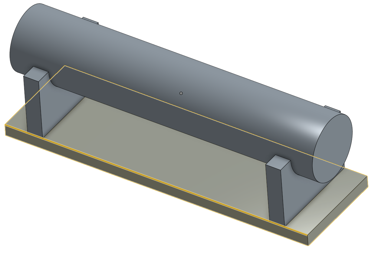 Is there a good way to do this in a multibody Part Studio? I see that I could create a copy of the saddle and then translate the copy, but I don't see how this would work if I wanted to connect the saddle locations to features on the cylinder. Am I missing something in how the workflow in Onshape is supposed to work?
Is there a good way to do this in a multibody Part Studio? I see that I could create a copy of the saddle and then translate the copy, but I don't see how this would work if I wanted to connect the saddle locations to features on the cylinder. Am I missing something in how the workflow in Onshape is supposed to work?
Tagged:
0
Answers
In some situations you may use a layout sketch, with entities mirrored, and use those entities to drive the location of features or parts, but in this case, I would suggest modelling one saddle and then mirroring the resulting body.
If there are some features of the saddles which are NOT symmetrical in the same way as their position is, (perhaps they're both shelled from the same end) then that feature would be added after the mirroring, to both bodies alike.
1. Draw a circle
2.Draw some horizontal lines give "Equal to" constrain with line which is used to make circle
3.Make sweep
4. Then make a plane with end line used for sweep using line point method
5.Make saddle using that plane.Then mirror the saddle and cylinder.
6.Use Boolean for cylinder to make single
7. Then make mounting plate
Finally if you edit the radius value,all depending component will be update automatically
) swept it. Why didn't you just extrude the cylinder just not as much and then make the rectangle and then move the extrude over?
The person who devised that method was @Narayan_K
Now sweep curves are made of small line with length equal to radius of the cylinder so whenever you change the radius value sweep length also changes accordingly....