Welcome to the Onshape forum! Ask questions and join in the discussions about everything Onshape.
First time visiting? Here are some places to start:- Looking for a certain topic? Check out the categories filter or use Search (upper right).
- Need support? Ask a question to our Community Support category.
- Please submit support tickets for bugs but you can request improvements in the Product Feedback category.
- Be respectful, on topic and if you see a problem, Flag it.
If you would like to contact our Community Manager personally, feel free to send a private message or an email.
Patterns or texture on drawing, Sheet metal diamond plate
 rhys_skinner
Member Posts: 17 PRO
Hi,
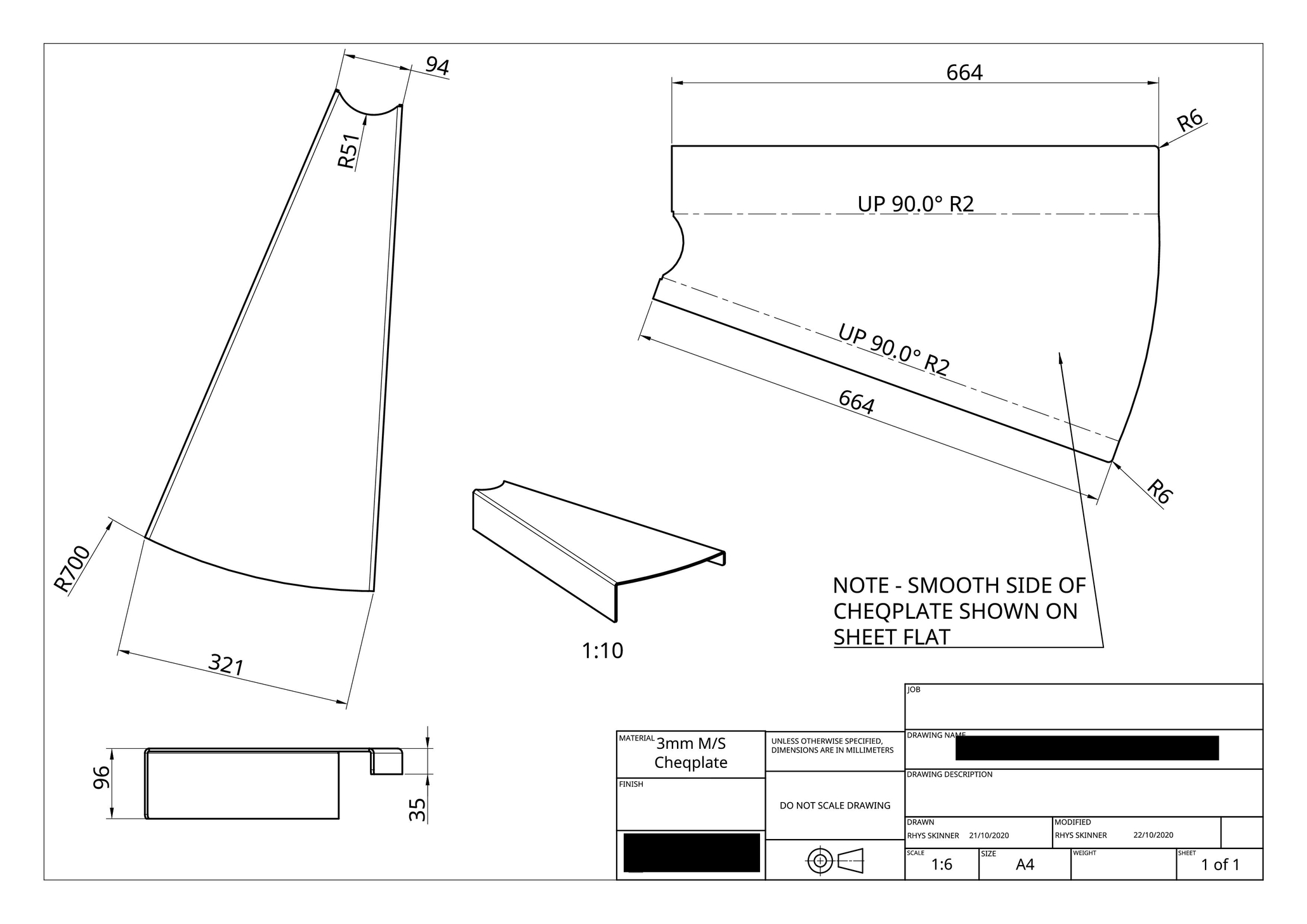
Wondering how I might add some texture to the drawing to represent diamond or checkerplate on a drawing and to specify within a "sheet metal" a top and bottom side so to speak Important for checkerplate fabrication or other sheet metal with feature sides like stainless etc.
My sheet metal fabricator was having issue with the clarity of the drawing attached as to what side of the checkerplate we are showing on the drawings (they nearly fabricated it inside out and/or laser cut it upside down). As you see it is somewhat confusing without any texture to represent the checkerplate. In the end I printed the drawing and drew texture with a pen on the Iso view, only to scan and email it back to them.
Any better solution or plans for improvement?
Thanks

0
Answers
Here's how I would do it:
- Model your sheet metal part however you want, but if it's in a part studio with others, derive it to a new part studio to add these appearances and make the drawing more easily
- Use the wire mesh custom feature to add a textured look to one of the sides (I know this isn't the most accurate look, but I'm just following the path of least resistance/least work
 )
) - Make the appearance wires into a single composite part and edit their appearance (optional)
- Create a drawing of the entire part studio to include the texture wires
- Add all of your dimensions, views etc.
- For the flat pattern, make sure the side that is textured faces down (you may need to switch between bottom/top view for it since the texture is not applied to the flat pattern)
https://cad.onshape.com/documents/8613d936df5621eff60f6ec6/v/66f2d5c4926bc6ecd10ecba4/e/d5d8976d26ce714695d3832aIt's not the cleanest solution, but I think it beats having to draw in the texture manually on paper. Hopefully, there will be a better workflow for this in the future.
I hope this helps!
@alnis is my personal account. @alnis_ptc is my official PTC account.