Welcome to the Onshape forum! Ask questions and join in the discussions about everything Onshape.
First time visiting? Here are some places to start:- Looking for a certain topic? Check out the categories filter or use Search (upper right).
- Need support? Ask a question to our Community Support category.
- Please submit support tickets for bugs but you can request improvements in the Product Feedback category.
- Be respectful, on topic and if you see a problem, Flag it.
If you would like to contact our Community Manager personally, feel free to send a private message or an email.
Relative constraints on dxf/dwg imports or copied sketches in general (Blocks in SW)
 Xano
Member Posts: 3 ✭✭
I need to emulate the relative constraints from SW called blocks, until the feature (hopefully becomes available)
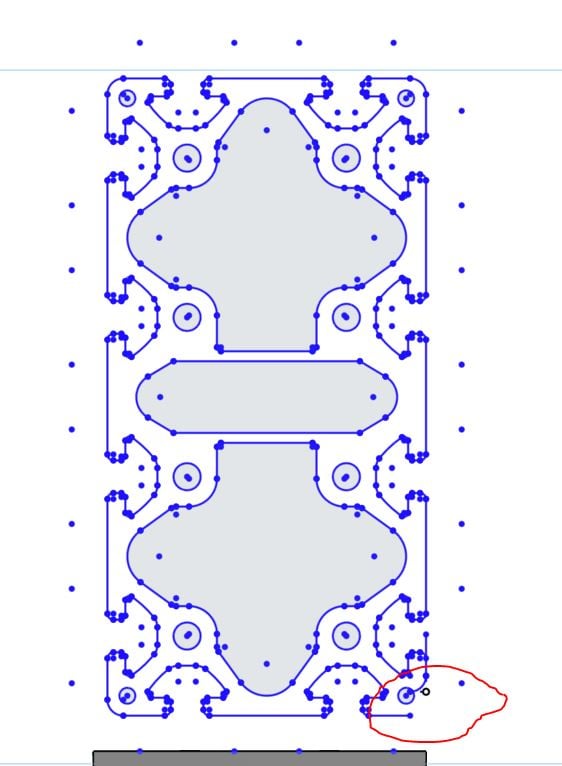
What I do now results in an unconstrained sketch. If I update anything that moves my "positioning point" the relative positioning between the copied/imported sketch elements and the "positioning point" gets broken
I have a dwg with a somewhat complex geometry that I wish to extrude in a parts studio, positioned relative to other parts.
1. I am importing the dwg to a sketch,
2. Convert/dimension a point relative to other parts in my sketch (positioning point).
3. Use transform with mate connectors to get the correct relative placement within the sketch.
I need the imported elements to move with the positioning point. (i don't really understand, why any of the imported elements move with the "positioning point" but some do - see the red circle).
The overall result is that the part studio I use for context, breaks with many updates on dimensions.

0
Comments
First off, if you post a link to your document and provide details on exactly what it is that you were trying to do, that could possibly help some here in the forum to give you some guidance
I’ve never used Solidworks. But I did look at a video regarding the blocks you mentioned
In essence, it looks like you’re able to group sketch elements, then scale, then use fills or hatches within the lines
So with Onshape, as long as there’s only one dimension on a sketch, you can change that one dimension, and the entire sketch will scale accordingly.
I’ve imported DWG’s into Onshape. I’ve scaled them up and down a bunch of times. Had no problems
After many updates in the dimensions, if all you end up with is the vertical line and arc being out of place, then probably the easiest thing for you do is just move those back into place and do your extrude
BUT,
Your statement — The overall result is that the part studio I use for context, breaks WITH MANY UPDATES ON DIMENSIONS.
I’m thinking to myself, If it were me that was making some part, where the dimensions are going to be changing MANY TIMES (UPDATES), where the sketch for the part references some other sketch or part, well I’d take the time to fully constrain all lines and arcs using numeric input &/or constrain by employing the coincident or use constraints to tie elements of the sketch to other sketches or parts
Looking at the image of the DWG posted, you could break it down to 16 identical parts, provided you make some modification in the center section of the DWG
- Import that solid into Onshape
- Sketch on the end face of the solid
- USE (project) the entire end face of the imported solid
Typically that should suffice and the resulting sketch will be fully constrained. I also like to hang a few driven dimensions on the profile for reference. Here is an example: https://cad.onshape.com/documents/567ebc8fcb4104cba426af99/w/ee0b16814fbbea5aae2d3a0d/e/84f6a89115e8fae2513c356b