Welcome to the Onshape forum! Ask questions and join in the discussions about everything Onshape.
First time visiting? Here are some places to start:- Looking for a certain topic? Check out the categories filter or use Search (upper right).
- Need support? Ask a question to our Community Support category.
- Please submit support tickets for bugs but you can request improvements in the Product Feedback category.
- Be respectful, on topic and if you see a problem, Flag it.
If you would like to contact our Community Manager personally, feel free to send a private message or an email.
Understanding inertia
 lars_rengersen
Member Posts: 32 ✭✭
For a part I am interested in the inertia of a crankhaft. I have modeled it, assigned material/density and in the assembly I have added the revolute mate so it turns nicely.

I was expecting a single value in kg/m2 for total inertia.
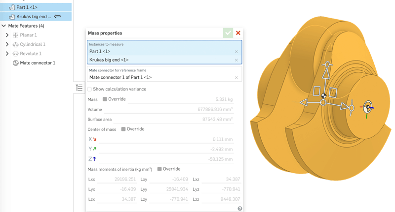
In use the 'Mass Properties Tool' but I do not understand the documentation.
"Moments of inertia - With respect to the common centroid of the selected parts (not the Part Studio origin) and reported using the densities of the materials assigned to the selected parts."
So my question is: How do I add such a common centroid?
And then the next question is, how do I interpret the "Mass moments of inertia" table?
What do these 9 values mean and is there a way to calculate that into the inertia of the model while rotating along the axle?
Thanks,
Regards,
Lars
Thanks,
Regards,
Lars
Tagged:
0
Answers
Instead, it gives you the mass moments of inertia around the center of mass with the axes being the assembly's x, y, z axes:
You can override the reference frame by specifying the mate connector to use as the (0, 0, 0) point as well as the x, y, z axes:
I think the documentation should be updated to state that it gives the values with respect to the center of mass rather than the centroid since these are different and it does seem to use the center of mass as the reference point, seeing as manually overriding the reference point to be at the centroid using a mate connector produces different results for the mass moments of inertia calculation (the right cylinder is 10x heavier than the left one):
@alnis is my personal account. @alnis_ptc is my official PTC account.