Welcome to the Onshape forum! Ask questions and join in the discussions about everything Onshape.

First time visiting? Here are some places to start:
  1. Looking for a certain topic? Check out the categories filter or use Search (upper right).
  2. Need support? Ask a question to our Community Support category.
  3. Please submit support tickets for bugs but you can request improvements in the Product Feedback category.
  4. Be respectful, on topic and if you see a problem, Flag it.

If you would like to contact our Community Manager personally, feel free to send a private message or an email.

Multi-body surfacing tactics/strategy

CGCAD_Engineer1CGCAD_Engineer1 Member Posts: 12 ✭✭
Hi all!

I'm on the verge of setting up a 'clean' model of a product we're developing and I'm trying to decide on a robust, efficient modeling strategy.
I tried finding info on modeling strategies/general guidelines/resilient modeling, but so far have not found much information specifically for Onshape. Hoping to get some input from the great hive mind :)

The sub-assembly I'm focusing on can be compared to a computer mouse; three parts (lets assume; body, left mouse button (symmetrical to RMB) and scroll-wheel) that share surface continuity. Let's also assume there is some grip texture on the buttons which needs to be the same on the body:
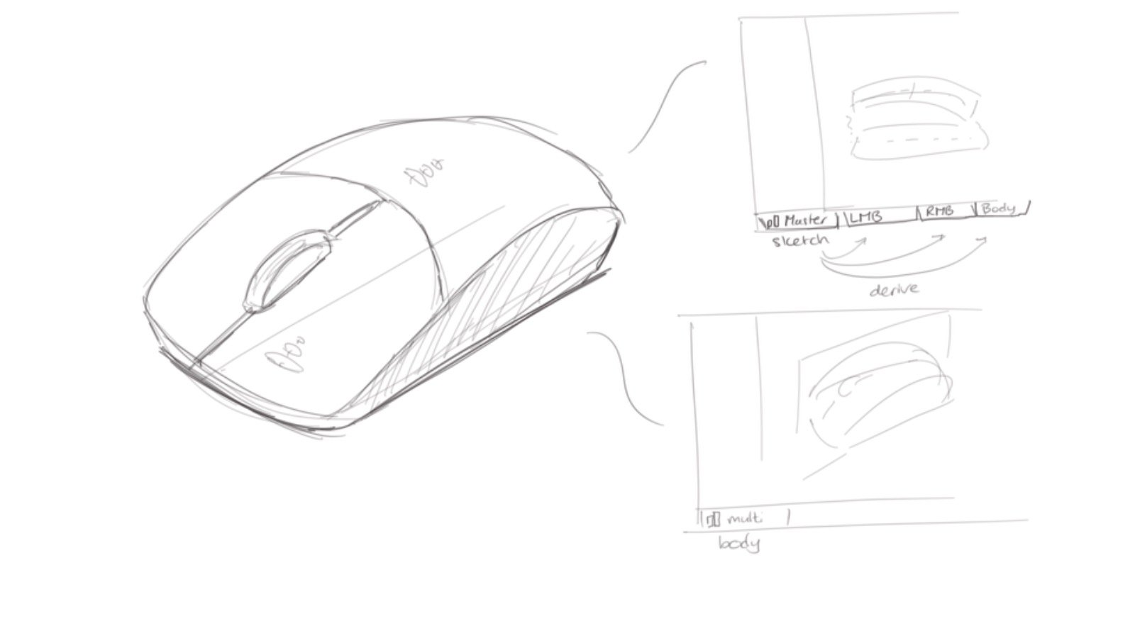
The goals to achieve and things to consider with the clean model are;
- Be able to quickly output several sizes of the product.
This should take into account that for example, a mouse button will become shorter and narrower, but its overall thickness stays the same for manufacturability.
- Eliminate errors and failing features.
Our models are a hodge-podge of features resulting from an elaborate prototyping and testing phase. This has created unstable surfaces/features which unexpectedly break down. I want to prevent errors in say, the mouse button, causing errors in the body.
- Capture design intent.
Models can get individual revisions, but stick to overall shape. So there's curvature continuity between mouse button and body. Also, say the grip texture is adjusted, it should be updated on both the mouse button and the body.
- Speeeeeed
Who doesnt? :P
But we also use these parts to create Tooling. Currently we Derive the part from its Functional design Document into a new Manufacturing design Document. Getting a short regeneration time on this Derive is a huge bonus.

I'm thinking of two approaches:
1) Setup a Master sketch/studio with all Sketches/Reference planes etc. in one Part Studio. Then import and use accordingly for each part in their respective Part Studios.
Pros:
- Each Part has its separate Part Studio, minimizing risk of one part failing leading to all parts failing.
- Can just Derive the one part we need for Manufacturing.
- Master sketch contains the features which should be the same across parts.
Cons:
- There's probably a ton of reference features in the Master sketch document..
2) Have one massive Part Studio using Multi-Body modeling. 
Pros:
- There are quite intricate mating surfaces between the parts, next to the shared surface continuity
- Clearly visible that similar features share similar dimensions (grip texture)
Cons:
- Loooooootts of features
- Deriving to tooling will import all Parts, then deleting the ones not needed for Derive (see Turbocharging Onshape). Causes increased regeneration times.


Looking forward to input/advice, tips&tricks, whatever you feel like sharing :)

Comments

  • tim_hess427tim_hess427 Member Posts: 648 ✭✭✭✭
    I've got a similar model and took approach number 2. It is a big, relatively slow part studio, but I think it's worth it.

    I'm not a surfacing expert, but it seems like one of the best ways to ensure curvature continuity between surfaces would be to model the whole surface and then split into its constituent parts, which would work in your approach #2. Also, even if you have tons of features in your master layout sketches, it seems like there would still be things that could affect multiple parts that couldn't be included in the layout sketches (I'm thinking things that could affect gaps between parts, or mating geometry like screw holes/bosses or snap-fits).

    Also, regarding the "one part failing causing all parts to fail" concern - I did deal with this some early on. However, I actually see it as a good thing that all parts are in one studio when this happens. If Part1 and Part2 need surface continuity and need to fit together, if one part breaks and requires edits, I want to know for sure that after I've fixed it, I've maintained the surface continuity and the parts still fit. I can do that if they're in the same part studio.

    Also, remembering to only derive versions should help mitigate any slowness in deriving parts for tooling design.

    I'm curious to see if others have experience with approach 1, but it just seems so much easier to control design intent, and consistency with approach #2.

  • matthew_stacymatthew_stacy Member Posts: 487 PRO
    @CGCAD_Engineer1 and @tim_hess427, this is potentially a good candidate for a collaborative design project.  Multiple users could review and critiquing each others work to develop high quality surface geometry and a concise, editable workflow. 
  • EvanReeseEvanReese Member, Mentor Posts: 2,139 ✭✭✭✭✭
    In the case of your example 3 parts, I'd probably just stay all in one part studio, and just be really aware of rebuild time. This will make configuring it later less cumbersome. This assumes the parts are about as complex as a mouse.

    If you judge your part complexity to be pushing your luck working in one studio, then some kind of Master Model approach is good. I often end up splitting the difference between workflow 1 and workflow 2. You don't have to go all-in with either. I'll model in a multi-part Master Studio, but am careful to only include features that define the part's interactions (over-all form, joints, screw bosses, surface transitions etc), but wouldn't include all of the details that only impact one part (fillets, label recesses, textures, stiffening ribs, hole patterns, etc). If I can only model half or a quarter of the model in the Master Studio, even better. The derivative studios can have a few parts too if that makes sense for the project. There's no rule about "one part per studio". Having a few parts in a studio does get you some efficiencies in the ability to fillet and mirror multiple parts at once. Once the Master Studio starts to solidify, it could be worth making the derive features reference a version for performance. You mentioned wanting similar grip textures across parts. I'd delay that step for as long as possible and when it has to be done, I'd set up variables with featurescript to drive it so you can reference the variables in multiple part studios. Or if the texture is more of an identical stamp in a few places, model it in a separate studio and use Super Derive to add it where you need it.
    Evan Reese
  • CGCAD_Engineer1CGCAD_Engineer1 Member Posts: 12 ✭✭
    Thanks for all the input! I was able to get some modeling in and got most of the modeling of the first of three parts done.
    This is my approach for now (extra detailed for future reference):

    I have three tabs in my Document;
    1. Global variables
    Uses a Custom Feature that defines variables which are then usable on each tab in a Part Studio; https://cad.onshape.com/documents/feb8818e93bf0b34319d3541/w/4038499ab977d6b0cc65aac1/e/8754b56a222528ae2157cd86
    In here I defined two sets of variables; 1) size dependent variables, such as lengths and widths. 2) Design intent variables - such as minimum wall thicknesses, and the dimensions of the 'grip' feature I mentioned earlier.

    2. Global skeleton
    In here I have my Master Sketches and Reference planes. These are only sketches/planes which are used by multiple parts.
    A new sketch is started for every different function, such as the different characterizing curves (for example, one being outer profile and the boneline).
    - In an earlier attempt I made one huge sketch with all functions combined, but the danger lurks that the sketch will blow up from one (unintended) relation. Furthermore, a colleague once had SolidWorks blow up because there were just too many sketch elements and relations in one sketch.
    - The drawback here is that it is 'invisible' which Sketch depends on which other Sketch for references. Thus it becomes dangerous to rearrange features...
    - I'm still debating whether to include mating surfaces here, or in each part's Part Studio. For now this Studio is clean with just sketches and planes. However, there needs to be a .2mm clearance between two mating parts. So I'm thinking of including the neutral surface here, and offset it 0.1 in each direction in each part's Part Studio..

    3. Individual part model
    As per Evan's suggestion this is where the general modeling is split into each part's individual modeling. Design intent is captured by using the Global variables wherever possible. And the Global skeleton helps in keeping the part continuity.
    - The sketches from the Global skeleton are Derived per feature. So there's a 'Boneline' sketch on the Right plane and one on the Front plane. One Derive feature imports both. There's a 1 second penalty in regeneration time per each Derive, but I think it's worth it in terms of overview and ease of being able to hide/show the separate sketches.
    > I found a Custom Feature which sort of enables this functionality, but haven't tried it yet. Interested to see the difference in regeneration times it will give. This will become especially interesting if I also decide to include mating surfaces into the Global skeleton studio, which will need (a) derive(s) as well.
    - As can be seen in the Feature Tree I tried to follow the guidelines of the 'Resilient Modeling Strategy' (learnrms.com). Gives a really clean Feature Tree :)

    So far, compared to the 'dirty' model we had, we went from ~110 adjusting features to 70 (in the part specific tab). And from 17s regen. time to 7s. And a much, much, much cleaner model B)

    Open questions for now:
    - Whether to include mating surfaces in the Global skeleton or the Individual part model?
    - How to allow for different size-variations of parts?
    This entails changing variables in the Global variables tab, then adjusting/finetuning overall shape of the shape-defining curves in the Global skeleton.
    Options to consider:
    A) capturing changed values in a Configuration table
    B) open new branch in the Version Tree for each size
    C) move size dependent variables from Global variables to Individual Part tab and duplicate tab for each size
    D) duplicate Document for each size
    I think there's a trade-off between being able to implement overall design changes easily for all sizes, but its more difficult to properly setup the model (option A) vs more work to make overall design changes but easier to control those changes across the board (option D).

    If anyone has any further suggestions/recommendations I'm happy to hear them.
    For now I'll work on the second part and see how the surface continuity holds up :)


  • EvanReeseEvanReese Member, Mentor Posts: 2,139 ✭✭✭✭✭
    Thorough strategy. Thanks for sharing. Some notes:
    • I recommend the "Own Sketch" feature to reduce the Derive features and improve rebuild time.
    • I think surfaces should be included in the top-level model. They are lightweight enough, and helpful for referencing across parts. It could be done either way though.
    • I think each size should be handled with configurations if the parts are really similar in most other ways than just size. Once you do it in a branch or copy, they aren't associated anymore. If you find you need to make a change to all of them, you'll have to do it to each of them manually.
    • for configuring it, you could make each of your global variables you want to change into an array, that you can address with a configured variable feature #index. You could even make certain variable values adjustable from the feature UI so you can configure them, similar to what I've done with Manufacturing Variables, but customized for this one project.
    Evan Reese
  • romeograhamromeograham Member, csevp Posts: 677 PRO
    One quick note: when your top-level studios AND your child part studios have many features (and even things like your Variables FS) the whole document slows down. I find if I have 3 - 5 related part studios with >200 features in each, the overall document performance can really suffer.

    Consider making a Version of the document and Deriving the Version of the top level reference parts into the Child studios....then when you make changes to your top level design intent - you can Version & Update the children again.

    For some complex interrelated Part Studios this can make a significant improvement in overall speed.

    You don't get instantaneous update of downstream parts when you change the parent, but you DO get snappier performance throughout (and it's WAY faster overall than designing in-context and updating contexts, which is inexplicably slow).

    I'd recommend doing this step (deriving Versions rather than Workspace parts) only after you've done most of the basic layout work...and when you shift your design time to the child Studios. That's when the document starts to slow down.

    One nice thing about this workflow is that, even though you don't get live, instantaneous updates of child studios, you DO get a nice blue dot reminding you to update the Derived features.

    Good luck!
  • CGCAD_Engineer1CGCAD_Engineer1 Member Posts: 12 ✭✭
    • I recommend the "Own Sketch" feature to reduce the Derive features and improve rebuild time.
    Ah, that's the one I had in mind yes. I'll test it and see what it does for performance :)
    • for configuring it, you could make each of your global variables you want to change into an array, that you can address with a configured variable feature #index. You could even make certain variable values adjustable from the feature UI so you can configure them, similar to what I've done with Manufacturing Variables, but customized for this one project.
    This would be so bomber to implement! Especially if you could get that Final-model preview slider at the bottom of the feature UI as well.. I think I can start with building a Configuration table first and then see if I can move it into an array.

    Consider making a Version of the document and Deriving the Version of the top level reference parts into the Child studios....then when you make changes to your top level design intent - you can Version & Update the children again.
    Thanks. That's the approach I took indeed. I started with deriving Versions, but during construction of all the Sketches it's easier to work from the open workspace to immediately see the changes.
    Funnily enough, at the moment the non-versioned Derive is faster than the versioned Derive (5s vs 7s rebuild). But I imagine this will change when I start work on the second part and insert more derives.
  • MichaelPascoeMichaelPascoe Member Posts: 1,989 PRO
    Own Sketch still works off of the derived right? How does it work?

    Learn more about the Gospel of Christ  ( Here )

    CADSharp  -  We make custom features and integrated Onshape apps!   Learn How to FeatureScript Here 🔴
  • EvanReeseEvanReese Member, Mentor Posts: 2,139 ✭✭✭✭✭
    it does, but it lets you call the derived feature only once, but split up the sketches into their own features. Otherwise, you can only show all or none of your derived sketches which is hard to use, or you have to do a new derive for each sketch which kills rebuild time.
    Evan Reese
  • MichaelPascoeMichaelPascoe Member Posts: 1,989 PRO
    Good to know. I definitely need to improve the rebuild time for larger studios.

    Learn more about the Gospel of Christ  ( Here )

    CADSharp  -  We make custom features and integrated Onshape apps!   Learn How to FeatureScript Here 🔴
  • EvanReeseEvanReese Member, Mentor Posts: 2,139 ✭✭✭✭✭
    I hear that! By the time you realize you need to it's often already too late. 
    Evan Reese
Sign In or Register to comment.