Welcome to the Onshape forum! Ask questions and join in the discussions about everything Onshape.
First time visiting? Here are some places to start:- Looking for a certain topic? Check out the categories filter or use Search (upper right).
- Need support? Ask a question to our Community Support category.
- Please submit support tickets for bugs but you can request improvements in the Product Feedback category.
- Be respectful, on topic and if you see a problem, Flag it.
If you would like to contact our Community Manager personally, feel free to send a private message or an email.
How to hide the shadow of a part used as a sketch plane
 michael_schaub
Member Posts: 9 ✭
Hello everybody,
for my sketches I often use an existing part as reference (plane) to create a new sketch.
I right-click on the surface of a part and choose "new sketch". So far, standard procedure.
I right-click on the surface of a part and choose "new sketch". So far, standard procedure.
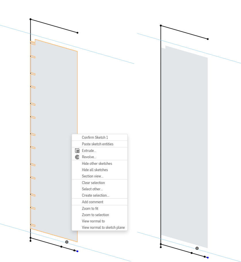
In this sketch however, the surface of the part appears as some kind of shadow. It is possible to extrude this shadow.
And here Onshape drives me crazy: When I want to extrude from my new sketch, I frequently click on this shadow instead on the sketch. It is literarely on the same plane.
Also, the edges of this shadow act as non-construction lines. Meaning, I have sometimes little holes in my parts because one of these almost invisible edges runs through my sketch.
I spent some serious amount of time fixing parts. With increased complexity this is just not sustainable any more.
Any help would be very much appreciated!
Best Regards,
Michael
Michael

Tagged:
0
Best Answers
-
 mahir
Member, Developers Posts: 1,319 ✭✭✭✭✭
When you use a surface as a sketch plane, Onshape will always infer its edges. The only way I know of to avoid this is to create a separate plane or mate connector on that surface and use that as the sketch plane instead. Specifically, the MC method is pretty straightforward since you can create MC's on the fly without adding extra features to the feature tree.3
 -
 mahir
Member, Developers Posts: 1,319 ✭✭✭✭✭
Adding a MC as a separate feature will definitely make it show up in the feature tree. But if you use the on-the-fly MC button next to the sketch plane box, there shouldn't be anything extra showing up in the feature tree.michael_schaub said:In my case, a Mate Connector will still show up in the feature tree.It does add additional bulk in the feature tree, which isn't nice. But as long as it works, I will save a lot of time.
2
Answers
Michael
Thats great!