Welcome to the Onshape forum! Ask questions and join in the discussions about everything Onshape.
First time visiting? Here are some places to start:- Looking for a certain topic? Check out the categories filter or use Search (upper right).
- Need support? Ask a question to our Community Support category.
- Please submit support tickets for bugs but you can request improvements in the Product Feedback category.
- Be respectful, on topic and if you see a problem, Flag it.
If you would like to contact our Community Manager personally, feel free to send a private message or an email.
Using loft tool to extrude off parallel to axis
 greg_lucas
Member Posts: 4 ✭
greg_lucas
Member Posts: 4 ✭
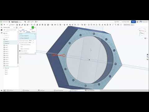
I'm trying to design a 3D Printed tool to make it easier for me to mark out steel tube notching for fabrication work I do at home. My idea is a cylinder with one end having a snug fit to the tube OD(i.e. +0.5~1mm) and the other end having a loose fit (+3~4mm) then a series of holes around the wall of the tool so I can insert some pins(2.4mm TIG filler rod) and I'd like the pins to follow the angle of the walls so that at the snug end it pushes down onto the tube for an accurate trace.
In the video it shows how some of the pin holes are failing to generate using the loft tool and some nearby holes get very skinny in the middle rather than the uniform 2.4mm end to end shown on the opposite side of the tool.
I think where my problem exists is the layout of the pin holes, I used the circular pattern sketch tool with the same offset (5mm) from the inner wall on both top and bottom faces to mark out the pin holes, and then same amount of holes on each face (48x) resulting in slightly tighter center measurements on the snug side. I used the same origin point for the prime pin hole (inline with the x axis on the rear of the tool) on both faces.
It's very frustrating not be able to drop all pin holes through in one go like I can using the extrude tool.
 https://youtu.be/CsHm7z_Jtg8
I'm getting decent working Onshape in block/circular shapes but I'm fairly new to working out of parallel/perpendicular on any CAD suites so definitely been bumbling my through. Guessing that I'm missing either something very simple or very much less likely might have stumbled across an opportunity for improvement.
https://cad.onshape.com/documents/394f3753ad25301d7e3c693d/w/7618e2c90071d3425d9ade13/e/bc69f69a31c274e21df425e7
In the video it shows how some of the pin holes are failing to generate using the loft tool and some nearby holes get very skinny in the middle rather than the uniform 2.4mm end to end shown on the opposite side of the tool.
I think where my problem exists is the layout of the pin holes, I used the circular pattern sketch tool with the same offset (5mm) from the inner wall on both top and bottom faces to mark out the pin holes, and then same amount of holes on each face (48x) resulting in slightly tighter center measurements on the snug side. I used the same origin point for the prime pin hole (inline with the x axis on the rear of the tool) on both faces.
It's very frustrating not be able to drop all pin holes through in one go like I can using the extrude tool.
https://youtu.be/CsHm7z_Jtg8I'm getting decent working Onshape in block/circular shapes but I'm fairly new to working out of parallel/perpendicular on any CAD suites so definitely been bumbling my through. Guessing that I'm missing either something very simple or very much less likely might have stumbled across an opportunity for improvement.
https://cad.onshape.com/documents/394f3753ad25301d7e3c693d/w/7618e2c90071d3425d9ade13/e/bc69f69a31c274e21df425e7
0
Comments
Looks like I had the right idea but the wrong execution. I'll give it another go now and report back with how I get on.
Thanks again!
Thanks very much for the help.
https://cad.onshape.com/documents/bbe7469c47815d8388fedcb8/w/16e2bace75322a36341735d9/e/af2ad35add8df93087e7dad9