Welcome to the Onshape forum! Ask questions and join in the discussions about everything Onshape.
First time visiting? Here are some places to start:- Looking for a certain topic? Check out the categories filter or use Search (upper right).
- Need support? Ask a question to our Community Support category.
- Please submit support tickets for bugs but you can request improvements in the Product Feedback category.
- Be respectful, on topic and if you see a problem, Flag it.
If you would like to contact our Community Manager personally, feel free to send a private message or an email.
Help with a 'tangent' mate
 dr_hutchinson
Member Posts: 10 ✭
If you look at the public document;
1-tool alone.step
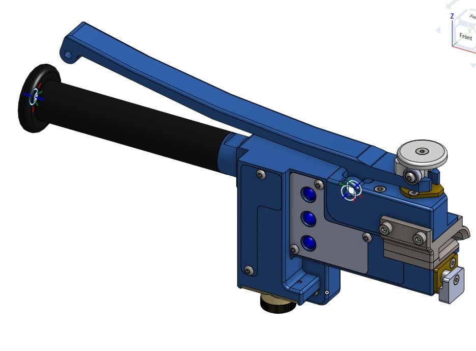
Can anyone suggest how you apply a tangent type mate to one of the bearings and the upper contact disk, so that when the handle is pulled the contact disk is raised. Dare I say, that this is trivial in SW, but appears more difficult to implement in ONSHAPE?
Thanks,
Barry.

1-tool alone.step
Can anyone suggest how you apply a tangent type mate to one of the bearings and the upper contact disk, so that when the handle is pulled the contact disk is raised. Dare I say, that this is trivial in SW, but appears more difficult to implement in ONSHAPE?
Thanks,
Barry.

0
Answers
If you look back through recent posts, there have been several on ways to achieve similar aims, with the words "tangent mate" in the title. There is a link to a model by @philip_thomas in which he provides some examples.
https://cad.onshape.com/documents/6ba1e39775d942b78b0c84f1/w/cdfcad3a3d7f4565ad4ffef4/e/61db20db6c0b4197818cef4d
Many thanks,
Barry.
Went back to assembly used Planar mate +Solve and got the desired motion (hope it helps)
Indaer -- Aircraft Lifecycle Solutions
Another approach would be to set up a planar mate with a connector at the central axis of the bearings, and type in the radius of the bearing under "Offset" for that mate.
Effectively constraining the axle to remain the correct distance from the underside of the rolling-contact flange
The solution is EXACTLY as i show in my weldment example.
1) I added a mate connector to the 13x4x5 bearing in the part studio (look at the feature tree)
2) In the assembly i used a planar mate between that mate connector and the underside of the pull disk - BOOM DONE!
3) I changed a couple of the cylindrical mates to slider mates. This reduces the number of degrees of freedom in the system. This was not necessary, but just an example of good modeling - dont leave more degrees of freedom than you need.
4) I added (rotational) limits to mate Slider 2 to limit the motion of the lever (again not needed)
5) I renamed a couple of the key mate relations so that i could find them more easily (we (Onshape) need to work on improving this).
I hope this helps (here is the (public) document)
https://cad.onshape.com/documents/4228e5cabaa44cdea4579b76/w/0522ecc2ea1349238d98ea8f/e/47e1a8c3b5f64c818da7e46e
THANK YOU ONSHAPERS!
(although mine had limits too
Indaer -- Aircraft Lifecycle Solutions
Barry