Welcome to the Onshape forum! Ask questions and join in the discussions about everything Onshape.
First time visiting? Here are some places to start:- Looking for a certain topic? Check out the categories filter or use Search (upper right).
- Need support? Ask a question to our Community Support category.
- Please submit support tickets for bugs but you can request improvements in the Product Feedback category.
- Be respectful, on topic and if you see a problem, Flag it.
If you would like to contact our Community Manager personally, feel free to send a private message or an email.
Why can it Boolean when other parts geometry is surpressed?
 karl_mochel
Member Posts: 54 ✭✭
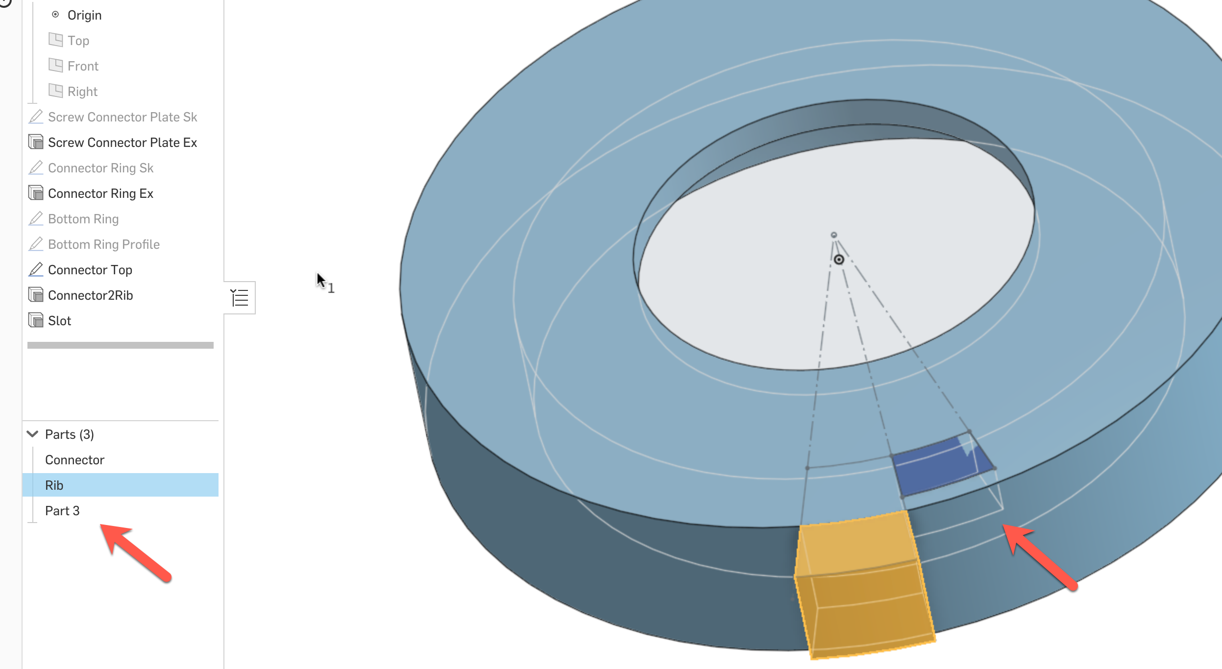
When Connector Ring Ex is not suppressed it doesn't Boolean Connecotr2Rib and Slot so I end up with Part 3.

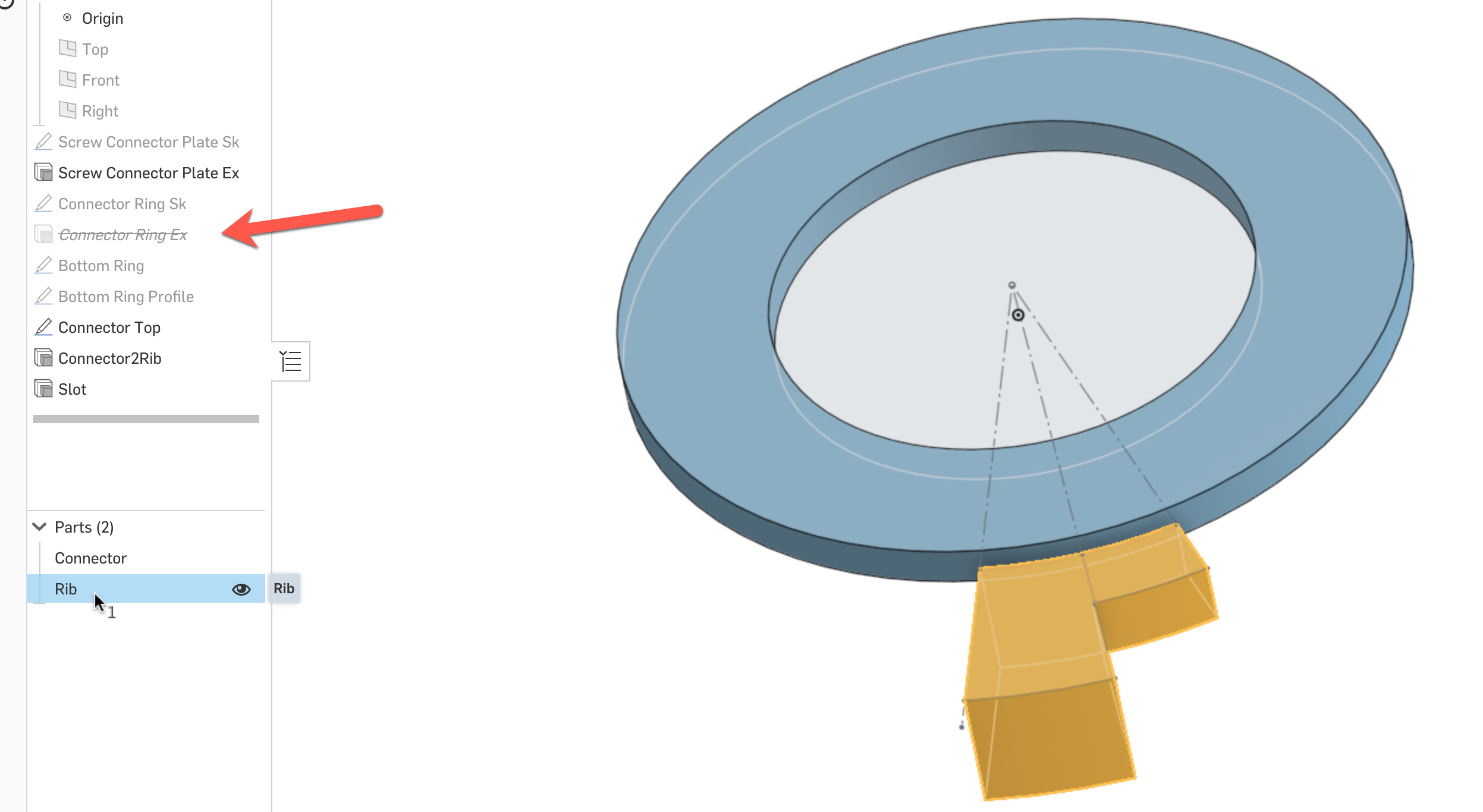
But when Connector Ring Ex is suppressed I get the desired result - Connector2Rib and Slot become one Part - Rib.


But when Connector Ring Ex is suppressed I get the desired result - Connector2Rib and Slot become one Part - Rib.

0
Comments
Then, if you're using "add" or "remove" - the feature will perform a Boolean union or subtract between the new body with any parts included in the "merge scope" box.
Its likely playing with those options your extrude features will solve the issue.
Slot - Add - correct Merge result is Rib
When Connector Ring Ex is Unsuppressed, the smaller part separates and becomes Part 3. When used as a Boolean the result is not the expected...Rib and Part 3 subtracted as a whole.
Every time you make a change, onshape rebuilds every feature in the list below the change. So, when you unsuppress Connector Ring EX, onshape will rebuild everything that comes after it, including your Connector2Rib and Slot features. These features may be acting differently with that part unsuppressed.
Here's what I think is happening:
- With Connector Ring Ex suppressed, your Connector Top sketch has one closed region.
- When you unsuppress Connector Ring Ex, the Connector Top sketch must be importing an edge from the Connector Ring Ex, creating two closed regions. But, when you extrude the Connector Top sketch, only one of those two regions is being extruded. Then, when you extrude the Slot, the two parts don't touch and don't merge.
So - either fix Connector Top sketch so that it doesn't use an imported edge from Connector Ring Ex, or change your Connector2Rib feature to extrude both regions instead of one.As a side note: Why are you suppressing/unsuppressing Connector Ring Ex? If you are just trying to hide a part, you can hover over its name in the parts list and click the little "eye" icon. Then, you won't run into downstream issues like this.
- For my editor spaces, the eye icons are only available for Sketches, not 3D parts...
Here is a link to the part if you want to play around with it.
https://cad.onshape.com/documents/2125aa07611f83e02e96aaf8/w/b311f32f43dfe8e7bbbb0493/e/a1ca32acd72561f15e7de695
Another workaround for this is to use an implicit mate connector to define your sketch plane (click the little mate connector icon next to the plane selection box). This will allow you to reference the face of a part without onshape making assumptions about using edges on that face.
To hide parts - make sure you're hovering over the part name in the parts list below the feature tree. A little "eye" icon should show up. If not, that's likely a bug. You can also right-click on parts and select "hide" from pop-up menu.
Originally I was selecting individual elements of the 3D objects to be the sketch plane. Now that looks problematic because I don't want any inferred assumptions, only explicit constraints.
On the Hide comments. Somehow I do not get the same experience you do.
A sketch has the Eye icon...
3D shapes do not...
...and there is no Hide in the menu.
The prototype print...