Welcome to the Onshape forum! Ask questions and join in the discussions about everything Onshape.
First time visiting? Here are some places to start:- Looking for a certain topic? Check out the categories filter or use Search (upper right).
- Need support? Ask a question to our Community Support category.
- Please submit support tickets for bugs but you can request improvements in the Product Feedback category.
- Be respectful, on topic and if you see a problem, Flag it.
If you would like to contact our Community Manager personally, feel free to send a private message or an email.
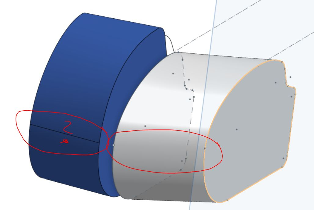
Is there a logic to seams between faces of a loft?
 wito_roz137
Member Posts: 5 ✭✭
https://cad.onshape.com/documents/96d2f63c98091d8538521590/w/9d7f859ef9f9ee0591254fbd/e/ba12e8bf890a79a99deb2a8b
I did 2 lofts. One ended up with a seam across the face, the other one did not. Now I cant draw a bridging curve as there is a edge on one but not the other. Sketches for both have splines tangent on both ends so all transitions between part of a sketch should be smooth. I don't understand why one of the faces have seam but not the other.


I did 2 lofts. One ended up with a seam across the face, the other one did not. Now I cant draw a bridging curve as there is a edge on one but not the other. Sketches for both have splines tangent on both ends so all transitions between part of a sketch should be smooth. I don't understand why one of the faces have seam but not the other.


2
Comments
Note that this does change the geometry of the part slightly:
the volume goes from 58495.69 mm³ to 58493.15 mm³ (difference of .0043% so idk if it's particularly important)
Just to reiterate, this is neither the best solution nor an answer to your question, but perhaps it is helpful nonetheless
After redrawing the arc.
There are a few ways that you can create construction geometry for a bridging curve. You can either split the face of each part with a plane, or create a sketch that uses the intersect option.
Plane inserted in the area where the split needs to be. (Point plane option)
Split faces using the plane. The edges formed by the split can now be used for the bridging curve.
Option 2.
I used the same plane as before to create a new sketch. With the "Intersect" sketch feature, select the faces of the part or parts to be intersected. This option will create the necessary construction geometry needed for the bridging curve, without changing the face geometry.
If you want learn more on how to use these advanced sketch constraints, check out the Advanced Part Design Learning Pathway, Advanced Sketching. Onshape Learning Center
Link to the copied document.
https://cad.onshape.com/documents/f62279415c32017e3b10597c/w/c6d91cfc9758b6cd4f5ee217/e/4128c2d938a11b1eeb2fea1a
Even if I redraw arcs without projecting them I still get the seam as soon as ends of arcs and splines on two sketches are aligned with each other. As soon As I make ends of arcs not aligned with each other on 2 sketches seam disappears.
I would really like to understand when seams like this are created to have a more predictable design flow. At the moment I do not understand how to predict if seam will or will not be created.
Thanks for showing me how to create geometry which can be used to make bridging curves.
FRC Design Mentor - Team 1306 BadgerBots
https://cad.onshape.com/documents/1d0963ec3ed860096bbe6c1b/w/b4c844efbb4cb4d094530d8c/e/1d947eb0365c03b1e0c3cf79
The Onsherpa | Reach peak Onshape productivity
www.theonsherpa.com