Welcome to the Onshape forum! Ask questions and join in the discussions about everything Onshape.
First time visiting? Here are some places to start:- Looking for a certain topic? Check out the categories filter or use Search (upper right).
- Need support? Ask a question to our Community Support category.
- Please submit support tickets for bugs but you can request improvements in the Product Feedback category.
- Be respectful, on topic and if you see a problem, Flag it.
If you would like to contact our Community Manager personally, feel free to send a private message or an email.
Importing text as lines
 joseph_newcomer
Member Posts: 101 ✭✭✭
joseph_newcomer
Member Posts: 101 ✭✭✭
I have the following problem: I want to extrude a letterform into a face. The problem is that the selection of fonts is too limited; I need to use a particular font on my machine. The font is called "Berlin" and is characterized by uniform thicknesses of all features. I need a font that has this because what will be run through the cut will be some EL wire. Note that I will only be using digits and they will not have any wires "overlapping".
To do this, I have to "insert" the wire in specific places. To do this, I had created the digits in CorelDraw and exported them with "text as curves". The intent is to read one of these in to OnShape, place the curves on the Sketch I am working in, join a line from the bottom to the digit, Note that the optimum point to join for some digits is not the bottom of the digit. However, this digit illustrates the point.
Here is the digit drawn in CorelDraw 2021:


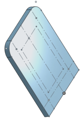
What you see below is Sketch 1 extruded to a 1/8" acrylic part. The front surface of this part is where Sketch 2 is placed, and I want to extrude it as a much thinner piece, only as thick as the EL wire. Then a third piece like this would be the front. I have been told by an OnShape user that all I need to do is select the face and "Export as DXF" to get a drawing I can send to the laser cutter, so I think the second half is going to be easy. Now all I have to do is create the faces to export.
The dotted line in the CorelDraw drawings is the sizing/position box and it is in its own layer. The OnShape drawing has the same-sized box in the same position. Now, in CorelDraw, I can create a rectangular object and "Weld" it to the digit, which produces the right-hand picture. The channel needs to be wider to allow for the EL wire splice (size yet to be measured). What I want to do is place either the digit or the digit-plus-access-cut on a sketch and extrude it to a 0.090" thickness (the closest thickness acrylic I could find to the EL wire diameter). Then on top of this there will be another layer of acrylic so the digit is sandwiched between two pieces of acrylic. All the layers will be cut on a laser cutter and will have a set of four holes (not yet in the drawing, although the points for placing them are there) which will allow me to bolt the layers together.
I can accept several solutions.
Yes, I know that 4, 6, 8, 9 and 0 produce loose parts, but one of the reasons for choosing the font I did was that the loose parts fit snugly against the EL wire and once clamped together there is ideally no problem (he said, with naïve optimism).
I have been using OnShape for less than a month, with a remarkable lack of success of importing the hundreds of Inventor parts and assemblies I did over the last several years, but Autodesk changed their free license policy. I'm retired, and their prices are beyond my reach. So assume that I barely understand what I am doing (in spite of the truly excellent tutorials, I keep finding questions I can't answer without a lot of exploration). However, this set of questions did not have any solutions after several hours of Web search. And I have been doing 3D design using Inventor for about eight years, so I am not a beginner at 3D design, just at using OnShape.
Thanks in advance.
To do this, I have to "insert" the wire in specific places. To do this, I had created the digits in CorelDraw and exported them with "text as curves". The intent is to read one of these in to OnShape, place the curves on the Sketch I am working in, join a line from the bottom to the digit, Note that the optimum point to join for some digits is not the bottom of the digit. However, this digit illustrates the point.
Here is the digit drawn in CorelDraw 2021:
What you see below is Sketch 1 extruded to a 1/8" acrylic part. The front surface of this part is where Sketch 2 is placed, and I want to extrude it as a much thinner piece, only as thick as the EL wire. Then a third piece like this would be the front. I have been told by an OnShape user that all I need to do is select the face and "Export as DXF" to get a drawing I can send to the laser cutter, so I think the second half is going to be easy. Now all I have to do is create the faces to export.
The dotted line in the CorelDraw drawings is the sizing/position box and it is in its own layer. The OnShape drawing has the same-sized box in the same position. Now, in CorelDraw, I can create a rectangular object and "Weld" it to the digit, which produces the right-hand picture. The channel needs to be wider to allow for the EL wire splice (size yet to be measured). What I want to do is place either the digit or the digit-plus-access-cut on a sketch and extrude it to a 0.090" thickness (the closest thickness acrylic I could find to the EL wire diameter). Then on top of this there will be another layer of acrylic so the digit is sandwiched between two pieces of acrylic. All the layers will be cut on a laser cutter and will have a set of four holes (not yet in the drawing, although the points for placing them are there) which will allow me to bolt the layers together.
I can accept several solutions.
- Is there a way for me to specify the font as one of the fonts on my machine? I could upload it (it is licensed to allow this) and that would be part of the problem solved. The other half is then to be able to "weld" the access path to the digit. I could not find any way to convert text to curves, but I am quite new to OnShape, having fled Autodesk Inventor.
- Is there a way to export the digit from CorelDraw in a format that can be accepted by OnShape? I can export it with "text as curves" so the lines would just be lines. I could add the access path, trim and join the edges, and I would be done. Alas, all I can find is .dxf format, and the instructions for importing it give me a completely black drawing with a gray digit and I can't figure out what to do to get those lines on my sketch. Once placed, I could add the access path and join the parts.
- I could also do the line joins in CorelDraw and export the digit and its access path, but I have the same problem as above, not knowing how to get those lines onto my sketch.
Yes, I know that 4, 6, 8, 9 and 0 produce loose parts, but one of the reasons for choosing the font I did was that the loose parts fit snugly against the EL wire and once clamped together there is ideally no problem (he said, with naïve optimism).
I have been using OnShape for less than a month, with a remarkable lack of success of importing the hundreds of Inventor parts and assemblies I did over the last several years, but Autodesk changed their free license policy. I'm retired, and their prices are beyond my reach. So assume that I barely understand what I am doing (in spite of the truly excellent tutorials, I keep finding questions I can't answer without a lot of exploration). However, this set of questions did not have any solutions after several hours of Web search. And I have been doing 3D design using Inventor for about eight years, so I am not a beginner at 3D design, just at using OnShape.
Thanks in advance.
0
Answers
Once you import the DXF into Onshape, it'll be in it's own tab (it sounds like you've made it this far.). The next step is to create your new sketch for the character, then when you're editing your sketch, you can import the DXF into the sketch. There should be a drop-down for the "Insert Image" tool that allows you to insert a DXF or DWG.
Then, after insert the DXF, the first dimension you place will scale the the whole imported image uniformly.