Welcome to the Onshape forum! Ask questions and join in the discussions about everything Onshape.
First time visiting? Here are some places to start:- Looking for a certain topic? Check out the categories filter or use Search (upper right).
- Need support? Ask a question to our Community Support category.
- Please submit support tickets for bugs but you can request improvements in the Product Feedback category.
- Be respectful, on topic and if you see a problem, Flag it.
If you would like to contact our Community Manager personally, feel free to send a private message or an email.
Problem with revolute mates
 kristoffer_falk
Member Posts: 23 ✭✭
Hi
I need some input regarding revolute mates in the model I am working on.
It is a heavy transport module in scale 1:24, and I am trying to get the steering to work. The problem arises when I want to connect side A with side B. Steering from front to back (left to right in the drawing works fine).

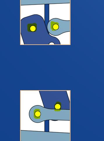
When I try to insert revolute mates on the yellow markings all other revolute mates turn red, and everything locks up. I have tried to make the mates in various order (start with the yellow ones, end with the yellow ones), but the result is the same.

Any input regarding this would be very welcome.
BTW: Is there a way to measure angles in the assembly? I would like to know the angle of A, B etc., so I get them to be in the correct relationship.

And here is the link to my document: https://cad.onshape.com/documents/8828ab805e7291ab8eefa40c/w/b0610ef777c02531deccf1dd/e/85b079a3e0d9b2ab44e88f8e
Regards
Kristoffer
I need some input regarding revolute mates in the model I am working on.
It is a heavy transport module in scale 1:24, and I am trying to get the steering to work. The problem arises when I want to connect side A with side B. Steering from front to back (left to right in the drawing works fine).

When I try to insert revolute mates on the yellow markings all other revolute mates turn red, and everything locks up. I have tried to make the mates in various order (start with the yellow ones, end with the yellow ones), but the result is the same.

Any input regarding this would be very welcome.
BTW: Is there a way to measure angles in the assembly? I would like to know the angle of A, B etc., so I get them to be in the correct relationship.

And here is the link to my document: https://cad.onshape.com/documents/8828ab805e7291ab8eefa40c/w/b0610ef777c02531deccf1dd/e/85b079a3e0d9b2ab44e88f8e
Regards
Kristoffer
0
Best Answer
-
 wayne_sauder
Member, csevp Posts: 631 PRO
The 2 faces are offset slightly that is the reason the revolutes will not work. The simplest thing to do is just use cylindrical mates for your last 2 mates.
https://cad.onshape.com/documents/c1325d005ef14f53abf5eae0/w/5c8043a4ed20836ee52e7290/e/2633add69fdd22072a3d3948
0
Answers
https://cad.onshape.com/documents/c1325d005ef14f53abf5eae0/w/5c8043a4ed20836ee52e7290/e/2633add69fdd22072a3d3948
Been working on the whole project for a few years now (on and off). I am going to CNC-mill the model in styrene to make the scale model.