Welcome to the Onshape forum! Ask questions and join in the discussions about everything Onshape.
First time visiting? Here are some places to start:- Looking for a certain topic? Check out the categories filter or use Search (upper right).
- Need support? Ask a question to our Community Support category.
- Please submit support tickets for bugs but you can request improvements in the Product Feedback category.
- Be respectful, on topic and if you see a problem, Flag it.
If you would like to contact our Community Manager personally, feel free to send a private message or an email.
Help with mate connectors and assemblies
 michael_stalls
Member Posts: 65 PRO
in General
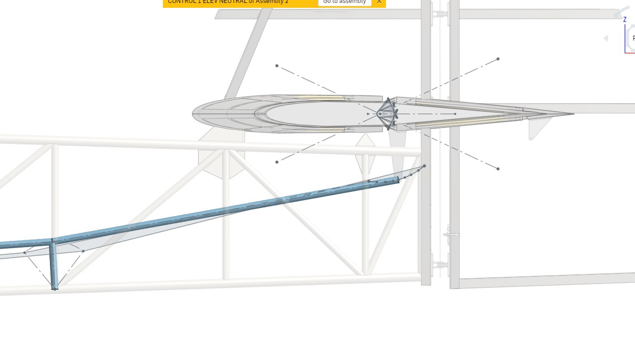
Hi im trying to design the pilot elevator control linkages for this aircraft project. i havent really done any mechanisms like this in onshape before and im not sure what mate connectors to use. If i link up the elevator pushrods (blue tubes) with revolute mates the whole mechanism comes out overdefined. If i use cylindrical mates the tubes move but go crazy. I have drawn up the paths of each tube ....the blue tubes in the screen grab represent the neutral position and the sketch lines indicate the max forward and aft travel of the elevator tubes. has anyone done anything similar to this
thanks
Michael

thanks
Michael


0
Comments
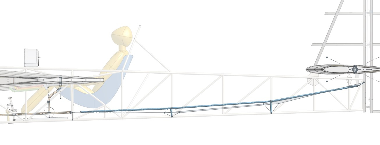
here is what it looks like so far. when i link two members together the motion is correct. but when i go to link in a third memeber it becomes overdefined. ive tried revolve, cylindrical , planar and ball and each time it comes out over defined and fails. is it possible to do linkages like this ? i sketched out the paths of each link and they should be the correct lengths to solve. I tried putting limits on the vertical supports so that it can solve but it doesnt seem to help.
thanks
michael
If I'm understanding your kinematic scheme correctly you purpose should be to have a pair of 4-bar linkage mechanisms with common linkage in the middle to synchronize motion. This linkage in the middle on my scheme marked by black arrow should have a cylindrical joint with the ground on one end and with a pair of maiting rods on another one to create the type of kinematics described above. But as I can see from screenshot you may not have a separate linkage there, but a joint part with one of the mating rods which creates a rigid triangle from the mated rods with zero degrees of freedom. And this may cause further issues.