Welcome to the Onshape forum! Ask questions and join in the discussions about everything Onshape.
First time visiting? Here are some places to start:- Looking for a certain topic? Check out the categories filter or use Search (upper right).
- Need support? Ask a question to our Community Support category.
- Please submit support tickets for bugs but you can request improvements in the Product Feedback category.
- Be respectful, on topic and if you see a problem, Flag it.
If you would like to contact our Community Manager personally, feel free to send a private message or an email.
Impossible in OnShape but possible in Autodesk IPT: Boolean operation failed to return a valid part
 trevor_curtis
Member Posts: 5 EDU
trevor_curtis
Member Posts: 5 EDU
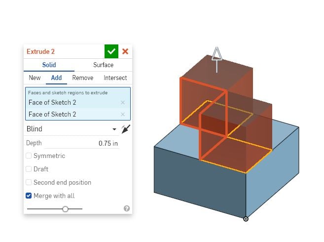
I am a high school engineering teacher. I started out in Autodesk Inventor. In that program, files are separated as parts and assemblies, etc. In Onshape, it seems that you could build assemblies inside part studios. There is a project we do where students create puzzle pieces that form to make a larger cube. Some of the parts that my students come up with are impossible to create in OnShape as one merged solid part. It always happens when two corners or edges come together with empty space on one or both sides. I get an error stating that boolean operation failed to return a valid part. I can create these same models in Inventor as one singular part, no problem. I don't understand why OnShape cannot create these models as one solid part when they are all connected through a joining body. Is there any solution for this? I have included images of two examples as well as a link to the file being used. I have tried multiple ways to create them as well as patterning. I have tried with and without "merge with all". Here is a link to the file: https://cad.onshape.com/documents/b2ea531c88ae07fcf1e23cdd/w/168c0f64537a353b0932764d/e/878a6945c242ed3dc8eb70ca
Here are some images:

Here are some images:
1
Comments
Simon Gatrall | Product Development, Engineering, Design, Onshape | Ex- IDEO, PCH, Unagi, Carbon | LinkedIn
I also tried what S1mon said and added a hole that was tangent to the surface of one of the models and it would not allow me to cut a hole, just like S1mon said. I would think that it would be possible to physically drill a hole in an object and have the edge of the hole be tangent to a surface.
I will accept that this is just the way it is in OnShape. It just seems like it should be possible to have a singular part like the ones I have demonstrated.
Also, think about a hole tangent to a surface. If you were to physically make that, what would you expect to happen? If the outside surface is continuous, that means there is a least 1 atom of thickness between the outside surface and hole (i.e. thickness > 0) OR there are missing atoms at some point along the surface and there is a gap of at least 1 atom wide (gap > 0).
Mathematically - I think it can also cause issues in the software because it has to keep track of where the "inside" and "outside" of a part is. A single edge that connects more than two faces throws a wrench into the works, so the parasolid kernel just says "nope! can't do that!" rather than deal with the complexity of allowing real-world impossible things to be modeled.
https://cad.onshape.com/documents/32c3355da96b467494123f9d/w/cbbafaa792be9f6fb924b59a/e/f21cf85daa244a6a8bf8fccb
Twitter: @BryanLAGdesign
bryan_lagrange, I used your advice and just used 0.748 instead of 0.75 for the rectangle dimensions and it will work for those instances. Thank you everyone.
https://cad.onshape.com/documents/7d17d14d4c7ef8b173987b1d/w/5dc2ba48cd28c392814c41d6/e/d6d1eab02d43776ae7523c19
When machining I make chamfers in this.
But when modeling cad data, the chmafers make us comfusing.
It is restriction of CAD, not less need of modeling.
Even so, I prefer prohibit of zero thickness in cad because such cases are rare .Zero thickness makes cad-system complex.
Even with EDM, I think you would need a gap in the center, which if you draw it that way Onshape will let you extrude it.
but it is different problem to want to make a model with zero thickness.
It is not necessary for me to make a model with EDM gap.
I have heard to development member of SolidWorks that parasolid kernel can treat a zero thickness. (I do not the detail.)
The following is my thought.
Pleat see modeling will be complex if permit zero thickness.
When no zero thickness, one edge have two adjacent faces.
If zero thickness, one edge can have four adjacent faces.
When you make a fillet on the edge, you must specify one of six types.
When one edge have 6 adjacent faces, how many types?
And more?
The biggest pain for me with the lack of zero thickness in Solidworks is not that I've ever wanted to model parts with zero thickness, but that cross sections would fail on some obvious place like the centerline because I happened to have some part with a hole tangent to the centerline. Sure, you can move the cross section plane some microscopic amount, but it's always seemed stupid. Somehow in Onshape they've managed to fix this issue, which is great (graphics only section?), but seems to be at the expense of being able to measure things on cross sections.
Simon Gatrall | Product Development, Engineering, Design, Onshape | Ex- IDEO, PCH, Unagi, Carbon | LinkedIn
Simon Gatrall | Product Development, Engineering, Design, Onshape | Ex- IDEO, PCH, Unagi, Carbon | LinkedIn
In my opinion, not teaching onshape to engineering students because it can't do something like zero-thickness features seems a little short sighted. It's just not something that's needed in an MCAD tool. For some, it could be a good thing and prevent an engineer from sending impossible things to the machine shop.