Welcome to the Onshape forum! Ask questions and join in the discussions about everything Onshape.
First time visiting? Here are some places to start:- Looking for a certain topic? Check out the categories filter or use Search (upper right).
- Need support? Ask a question to our Community Support category.
- Please submit support tickets for bugs but you can request improvements in the Product Feedback category.
- Be respectful, on topic and if you see a problem, Flag it.
If you would like to contact our Community Manager personally, feel free to send a private message or an email.
Is there a way to set the offset of a mate connector to a surface?
 james_howard360
Member Posts: 28 PRO
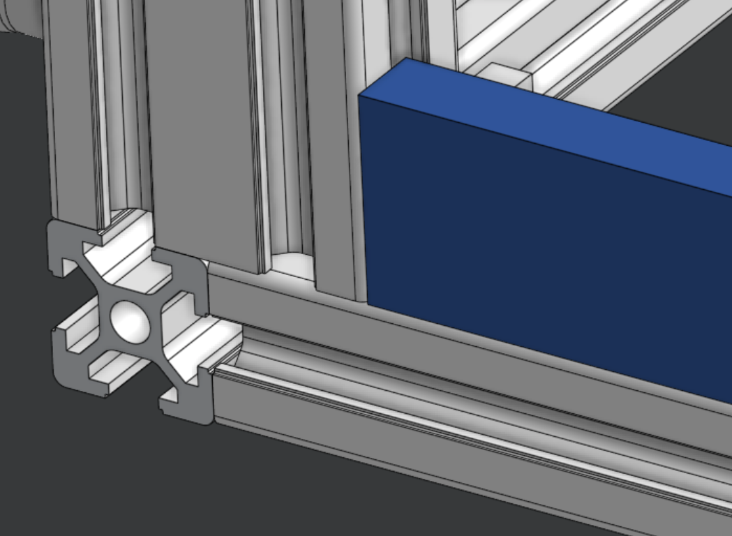
To mate the parts shown in the picture below requires 3 planar mates. OnShape says using a lot of planar mates is tough for the solver and can end up with broken or unsolved mates (which appears to be true; using too many planar mates in my assembly breaks the mate solver even though the mates are not conflicting). I'd like to use a fastened mate to align the corner of the blue block to a point at the intersection of the witness lines  at the end of the T-slot corner. It seems like the only ways to do that are A ) create a sketch on the end of the t-slot with the point to which I want to mate, or B ) add a mate connector to the point at the start of the fillet and offset by the radius amount.
This is a constant and common issue, so option A means creating a lot of sketches just to add mate connectors. Option B is hard-coding values and destroys the parametric nature of the assembly. Is there a way to create a mate connector and use a second plane as the offset so it updates dynamically with changes to parts?


 at the end of the T-slot corner. It seems like the only ways to do that are A ) create a sketch on the end of the t-slot with the point to which I want to mate, or B ) add a mate connector to the point at the start of the fillet and offset by the radius amount.
This is a constant and common issue, so option A means creating a lot of sketches just to add mate connectors. Option B is hard-coding values and destroys the parametric nature of the assembly. Is there a way to create a mate connector and use a second plane as the offset so it updates dynamically with changes to parts?


0
Comments
First and foremost, I use the "Extrude 8020 Profile" custom feature to create t-slot extrusion parts. Starting points for the extrusion profiles are sketched on one of the default planes, and the limits of the extrusions are defined by vertices in a sketch on an orthogonal plane. This approach places the extrusion parts in the desired geometric relationship.
Second, an extrusion assembly created as described above can be fully constrained by a group mate in the assembly after inserting the parts into the assembly, or with one or more groups plus fastened mates as needed to accommodate possible parametric changes. Fastened mates without offsets can be created between the implicit mate connectors on the adjoining faces of a butt corner joint
Finally , one must generally resort to fastened mates with distance offsets to create a fully constrained assembly. This somewhat annoying necessity is mitigated some what by the fact that the dimensional uniformity of T-slot extrusions means that the offset values are limited to a few choices that cover nearly every circumstance. It's a simple matter to index the corner of an added part such as your blue block to the center of the hole in the extrusion end (x offset = 3/4 extrusion width; y offset = 1/2 extrusion height). Another useful point to originate a mate is on the flat surface at the bottom of the extrusion slot- this value is a constant for every series of extrusion.