Welcome to the Onshape forum! Ask questions and join in the discussions about everything Onshape.
First time visiting? Here are some places to start:- Looking for a certain topic? Check out the categories filter or use Search (upper right).
- Need support? Ask a question to our Community Support category.
- Please submit support tickets for bugs but you can request improvements in the Product Feedback category.
- Be respectful, on topic and if you see a problem, Flag it.
If you would like to contact our Community Manager personally, feel free to send a private message or an email.
Confusion about slider mates
 joseph_newcomer
Member Posts: 101 ✭✭✭
in General
I have two problems; I will submit another question for the second one.
For this one, I wanted to create a slider mate so I could reposition my servo on the backplate. The file link is
https://cad.onshape.com/documents/cd1c50678c1b377ca69e7bd7/w/9db17e8af11a8b04576676be/e/cccc756981714a03ed2605a3?renderMode=0&uiState=61d7cf0fc3cb70796723e875
and is a public document.
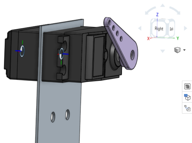
I've attached a screenshot:

What I want to be able to do is slide the servo up and down on the back plate, that is, in the Z-axis. A slider mate tells me that I select two points, the first one being the point on the back of the servo (visible in the screenshot) and the second one, the fixed point, is the one on the backplate (also visible). But it won't slide in the Z-axis (note the axes, which I carefully made sure were in the screenshot). Z is vertical. But it only moves in the Y axis (as you see, it has moved through the solid metal, which is going to be hard to do In Real Life). Why didn't it do what was promised and give me motion in the Z-axis. (Suggestion: why are the axes predetermined? I should be able to, in the dialog, select the axis along which I wish to have motion). I have no control over the axes of the servo, which I downloaded from GrabCad; I do have control over my axis system, and that's the one it should be using (or, better still, let me decide what the axis of motion is!).
The sliding will be done at design time; it is not dynamic during operation.
Also, a couple of the mates complain that they need two mate points, yet that's how I got them, was giving two mate points. It was happy enough to create them, then complained that I didn't have two mate points. So I'm confused.
Thanks in advance
Joe
For this one, I wanted to create a slider mate so I could reposition my servo on the backplate. The file link is
https://cad.onshape.com/documents/cd1c50678c1b377ca69e7bd7/w/9db17e8af11a8b04576676be/e/cccc756981714a03ed2605a3?renderMode=0&uiState=61d7cf0fc3cb70796723e875
and is a public document.
I've attached a screenshot:

What I want to be able to do is slide the servo up and down on the back plate, that is, in the Z-axis. A slider mate tells me that I select two points, the first one being the point on the back of the servo (visible in the screenshot) and the second one, the fixed point, is the one on the backplate (also visible). But it won't slide in the Z-axis (note the axes, which I carefully made sure were in the screenshot). Z is vertical. But it only moves in the Y axis (as you see, it has moved through the solid metal, which is going to be hard to do In Real Life). Why didn't it do what was promised and give me motion in the Z-axis. (Suggestion: why are the axes predetermined? I should be able to, in the dialog, select the axis along which I wish to have motion). I have no control over the axes of the servo, which I downloaded from GrabCad; I do have control over my axis system, and that's the one it should be using (or, better still, let me decide what the axis of motion is!).
The sliding will be done at design time; it is not dynamic during operation.
Also, a couple of the mates complain that they need two mate points, yet that's how I got them, was giving two mate points. It was happy enough to create them, then complained that I didn't have two mate points. So I'm confused.
Thanks in advance
Joe
0
Comments
How do you plan to make the part? is the sliding capability going to be there in real life? If so then why not design your part accordingly and use an appropriate mate. The slider mate is normally used for things like pins in holes etc. If you just want to explore ideas the I would use a planar mate and set the limits.
Also, note that the mate coordinates have no connection to the view cube, the mate coordinates, and orientation are established in the model space in which the parts were created and I think I am correct in saying z is always perpendicular to the face unless you use an edge or vertex. I'm not sure If that makes any sense, maybe someone else can chime in and better explain default mate behavior.
I find it helpful to keep in mind that the names of the mate types are more like "example" or "typical" use but it helps to think purely in terms of what degrees of freedom they allow to figure out "other uses".